an endless golden thread, droid style

Well, you know how it is. You buy a tablet, because tablet. Then what?

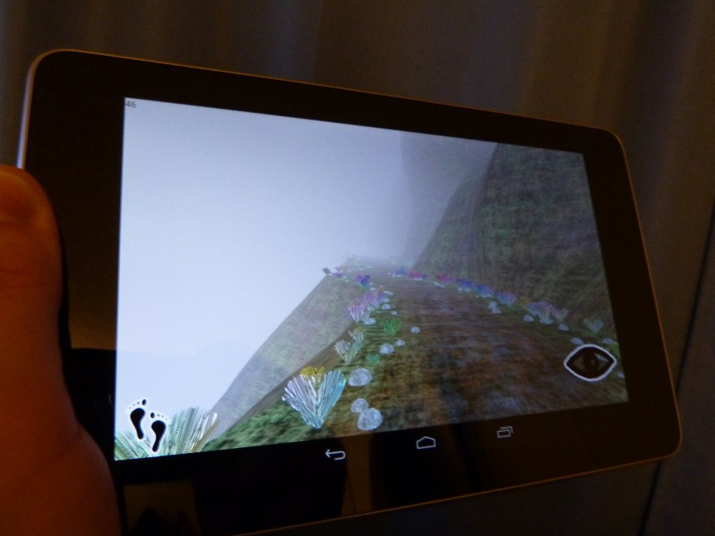
I’ve ported my Soar toolkit and my thread demo over to Android. Sources can be found at my GitHub hangout and are free to do whatever you want with.

Android’s not a bad enviroment, and the GUI and OS concepts should be familiar to anyone who’s ever done native application work. Java is…Java. It’s clunky but sort of comfortable after a while, like a bulky jacket on a cold morning, and takes forever to put on. Oh, it looks like something your mother picked out for you. Ha! Buuuuurn.

As WebGL wraps OpenGL ES—also like a jacket of some description—I had little difficulty porting the code. I missed closures and first-order functions, but it wasn’t hard to get back into the Java mindset of packing everything into little class boxes.

In fact, the only area I had to strain my brain was shaders. The GLSL code ports directly, but mobile GPUs aren’t anywhere near as powerful as their desktop pals, so my original shaders lagged horribly. I had to cut them down just to get 30 fps. Then, I found surfaces turning blocky and pixelated over long distances. I texture some surfaces using absolute positions instead of texture coordinates in order to achive long-period patterns. Works fine on the desktop, but on a mobile GPU, the loss of floating point precision has a noticable effect as the numbers get bigger. I have a workaround in place which uses a modulus of the position, but it looks kind of messy in places. Ah well.

again with the marching

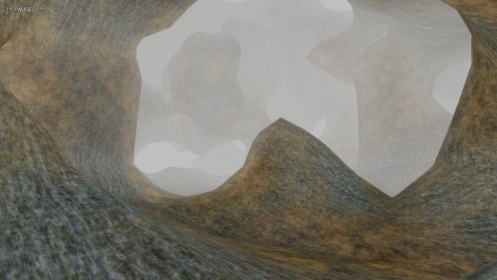
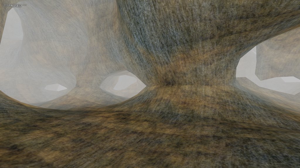
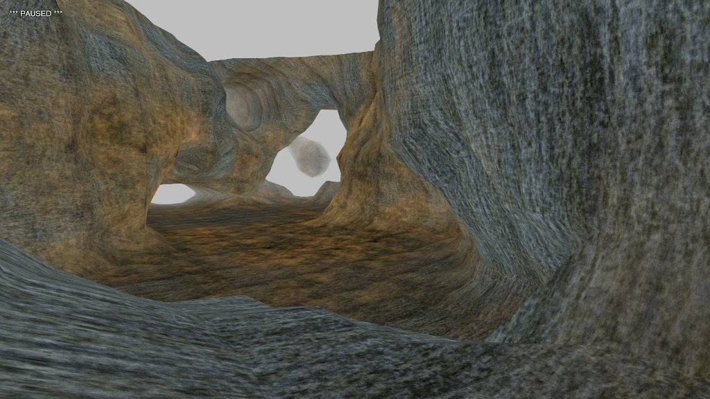
I have to admit that when generating isosurfaces, I’ve come to prefer polynomial-trigonometric functions over noise arrays. Where noise gives samey-looking blobs in all directions, PTFs (polytrigs?) provide structure and asymmetry at low cost.

Here’s the source function I used to generate those surfaces.

var k1 = M.rng.get(-1, 1);
var k2 = M.rng.get(-1, 1);
var k3 = M.rng.get(-1, 1);

var source = function(x, y, z) {
	if (y < 0.1)
		return -1;
	var a = x + y + k1;
	var b = y + z + k2;
	var c = z + x + k3;
	var d = a + b * c;
	var e = a * b + c;
	return Math.cos(a * d + b * d + c);
};

Rolling up a few random offsets gives us a variety of surfaces. The specifics of the math don’t matter: I just want a polynomial that’s complex enough to be interesting. We take the cosine to smooth the results and limit them to the range (-1, 1).

For the field function, I’ve dropped the cube-based point field thingy I used in the last couple of posts in favor of a modified 3D interpolator.

var field = function(x, y, z) {

	function lerp(y0, y1, mu) {
		return mu * y1 + (1 - mu) * y0;
	}

	var xi0 = Math.floor(x);
	var mux = x - xi0;

	var yi0 = Math.floor(y);
	var muy = y - yi0;

	var zi0 = Math.floor(z);
	var muz = z - zi0;

	var xi1 = xi0 + 1;
	var yi1 = yi0 + 1;
	var zi1 = zi0 + 1;

	var i1, i2, i3, i4;
	i1 = lerp(source(xi0, yi0, zi0), source(xi0, yi0, zi1), muz);
	i2 = lerp(source(xi0, yi1, zi0), source(xi0, yi1, zi1), muz);
	i3 = lerp(i1, i2, muy);

	i1 = lerp(source(xi1, yi0, zi0), source(xi1, yi0, zi1), muz);
	i2 = lerp(source(xi1, yi1, zi0), source(xi1, yi1, zi1), muz);
	i4 = lerp(i1, i2, muy);

	return lerp(i3, i4, mux);
};

It’s a stripped-down version of the code I use to generate isosurfaces from noise arrays. It uses linear rather than cosine interpolation. Initially, I made the change to improve its performance, but found that it also allowed a greater variety of shapes.

a better world

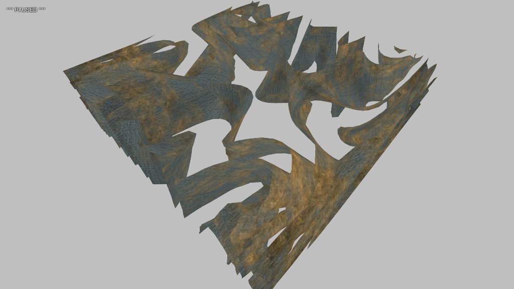
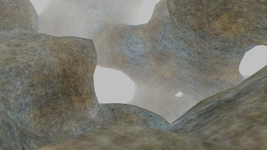
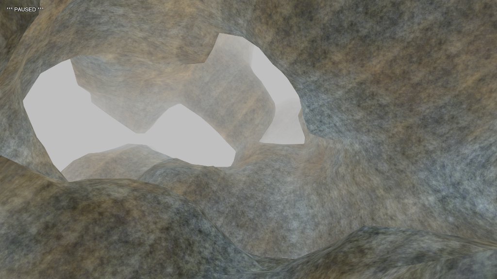
Following up on my last post, I was able to generate a scene with less eye static.

There are two important changes under the hood. One is the noise generator that we sample to construct the field. I removed the huge multipliers and offsets from the old function, leaving the essential trig/polynomial stuff.

var v = Math.cos(x0 + Math.sin(y0 + Math.cos(z0) * x0) * z0);

What remains can’t properly be called a noise function. If I remove the sampling code and graph the function itself, this becomes pretty obvious.

It’s all foldy and warpy, but it’s not noisy. There is structure here. It comes out in the end.

The other change is the addition of a “floor”. I’ve noticed that when I generate 3D environments that go off in all directions and try to navigate them, I become disoriented quickly. I’ve been toying with the idea of creating a game based in such an environment, and this is the biggest obstacle. Humans evolved in a gravity well. Even in virtual reality, we need a sense of where “down” is. Take that away, and I’m not sure anyone will want to play for very long.

this universe needs a plant

I’ve been marching the cubes again, looking for interesting spaces to march them through. Most of these spaces have been based around Perlin noise generators, which simulate smooth functions by interpolating across a grid of random numbers. They do a fine job of creating a blobby-looking world, assuming you like that sort of thing.

Hm. What else you got?

The WebGL Caves demo uses a point field to fine effect, so I thought I’d give that a try. I managed to create things I liked, but I was missing one of the benefits of a noise generator: it’s usable everywhere. Point fields tend to be limited to a finite set of source points. (I suspect an infinite set would have difficulty operating in polynomial time.)

Of course, you can always cheat. Cheaters always prosper, right?

I needed a field function that could simulate an infinite number of points. To keep it simple, I decided to map these points to integral boundaries. (If this were a film, you’d be hearing ominous foreshadowing music right about now.)

// generate the upper and lower bounds 
var x0 = Math.floor(x);
var x1 = x0 + 1;
var y0 = Math.floor(y);
var y1 = y0 + 1;
var z0 = Math.floor(z);
var z1 = z0 + 1;

The (x, y, z) point is whatever real point in space we want to get a field value for. I obtain the integral upper and lower bounds. From these, I can build a cube of points that surround the supplied point, and generate a sum of contributions to the total field.

// sum over the contributions to the field
// from each point on the cube
var f = 0;
f += con(x0, y0, z0, x, y, z);
f += con(x0, y0, z1, x, y, z);
f += con(x0, y1, z0, x, y, z);
f += con(x0, y1, z1, x, y, z);
f += con(x1, y0, z0, x, y, z);
f += con(x1, y0, z1, x, y, z);
f += con(x1, y1, z0, x, y, z);
f += con(x1, y1, z1, x, y, z);

The con() function supplies a value for the source point, and divides that value by the inverse square of the distance between the source point and the point in space, thus implementing a simple potential field.

function con(x0, y0, z0, x, y, z) {
	var dx = x - x0;
	var dy = y - y0;
	var dz = z - z0;
	var d2 = dx * dx + dy * dy + dz * dz;
	
	var v = Math.sin(x0 * 128374.123 * Math.sin(y0 * 2183423.234 * Math.sin(z0 * 94823921.2834 + 19873923.9384 * x0) + 2384923.398293 * z0) + 48392034.837439 * y0);
	return v / d2;
}

The weird nested sines thing serves as a sort of noise function. It seems to work well for integral points, and it’s defined everywhere. I also tried lookups of random numbers but that actually ran slower. I’m assuming the nested trig function is JIT-compiled to a few floating point instructions with register access, whereas the table lookup requires hitting the cache.

The end result of all this clever trickery?

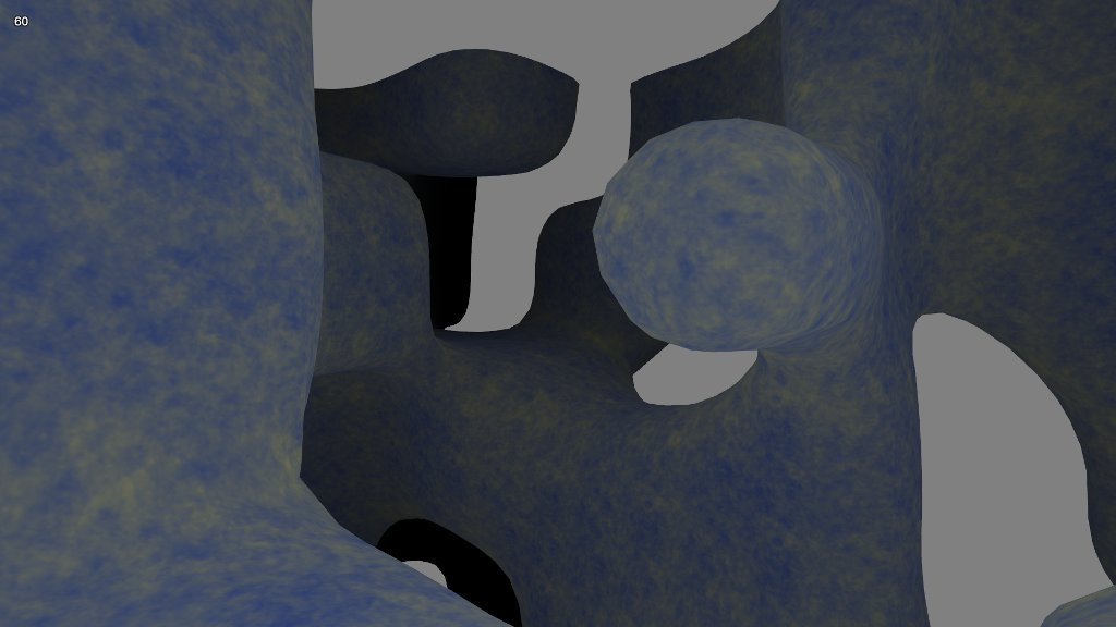
Why, it’s another blobby-looking world!

Okay, they’re not exactly the same. The cheater field tends to produce tunnel-like structures instead of blobs, and its surfaces are a little rougher. These differences aren’t that obvious at a casual glance, however. I don’t see it as a viable alternative to using a Perlin noise field.

What went wrong? Well, even though I’m summing over field contributions rather than interpolating, I’m still relying on random noise sampled at integral boundaries. This underlying source tends to express itself no matter what the technique, resulting in what I’ve come to regard as visual monotony. Though the surface you see is actually different everywhere you look, it doesn’t matter. The essential form is always the same.

Now, if I could break up that visual static—clump it, cluster it, gather it all into little structures—I might have something worth looking at. We’ll see where that leads.

an endless golden thread

Ever since Web Workers arrived, I’ve been thinking about how to use them in my own stuff. I’ve been developing a game that involves a procedurally generated cliff path and I want that path, like all good things, to go on forever.
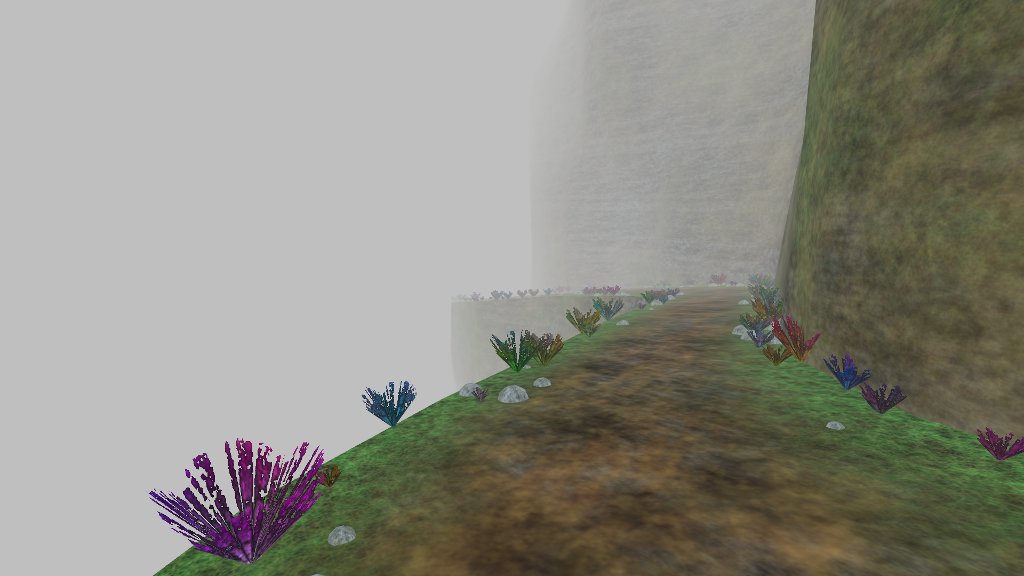
(Want to see it in action? Try the Live Demo. WSAD moves, Q for fullscreen.)

I update the scene every time the player moves a set distance from the last update. If I do this within an animation frame, I’m going to get a drop in frame rate, and possibly a visible skip in the game experience. That’s an immersion killer. Workers to the rescue!

Well, not so fast.

The GL context itself can’t be used in a worker thread, as it’s derived from a DOM object. I can’t update my display meshes directly, and I can’t send them back and forth—function members are stripped out when sending objects between threads. Only data is allowed. So: data it is. Generate updates in the worker thread, and hand the results over to the main thread for display. (I was worried that objects would be serialized JSON-style across thread boundaries, but Chrome and Firefox perform a higher-performance binary copy of the data instead.)

Creating a thread is simple enough.

T.worker = new Worker("thread.js");
T.worker.onmessage = function(e) {
	T.handle(e);
};
T.worker.onerror = function(e) {
	console.log("worker thread error: " + 
		e.message + " at line " +
		e.lineno + " in file " +
		e.filename);
};

Sadly, that error handler is all the debugging support you’re likely to get. Because the worker thread is running inside another page context, you can’t set a breakpoint in it. Back to the heady days of printf debugging! Ah, memories.

After creating the thread, I want to tell it to construct whatever objects it needs to fulfill my requests—in this case, the objects that describe the cliff path surfaces. There’s a problem, however, as I also need those objects in the main thread to handle collisions. I can’t share the surface objects directly as they contain function members. So, I create the surface maps, which are data-only, and ship those across.

// generate road and cliff surface maps
this.road.map = SOAR.space.make(128);
SOAR.pattern.randomize(this.road.map, T.seed(), 0, 1);
this.road.height = SOAR.space.makeLine(this.road.map, 6, 0.05);

this.cliff.map = SOAR.space.make(128, 128);
SOAR.pattern.walk(this.cliff.map, T.seed(), 8, 0.05, 1, 0.5, 0.5, 0.5, 0.5);
SOAR.pattern.normalize(this.cliff.map, 0, 1);
var surf0 = SOAR.space.makeSurface(this.cliff.map, 10, 0.05, 0.1);
var surf1 = SOAR.space.makeSurface(this.cliff.map, 5, 0.25, 0.5);
var surf2 = SOAR.space.makeSurface(this.cliff.map, 1, 0.75, 1.5);
this.cliff.surface = function(y, z) {
	return surf0(y, z) + surf1(y, z) + surf2(y, z);
};

// send the maps to the worker thread and let it initialize
T.worker.postMessage({
	cmd: "init",
	map: {
		road: this.road.map,
		cliff: this.cliff.map
	},
	seed: {
		rocks: T.seed(),
		brush: T.seed()
	}
});

On the thread side, a handler picks up the message and routes it to the necessary function.

this.addEventListener("message", function(e) {

	switch(e.data.cmd) {
	case "init":
		init(e.data);
		break;
	case "generate":
		generate(e.data.pos);
		break;
	}

}, false);

The initialization function uses the surface maps to build surface objects, plus a set of “dummy” mesh objects.

function init(data) {

	// received height map from main thread; make line object
	road.height = SOAR.space.makeLine(data.map.road, 6, 0.05);
	// generate dummy mesh for vertex and texture coordinates
	road.mesh = SOAR.mesh.create(display);
	road.mesh.add(0, 3);
	road.mesh.add(0, 2);

	// received surface map from main thread; make surface object
	var surf0 = SOAR.space.makeSurface(data.map.cliff, 10, 0.05, 0.1);
	var surf1 = SOAR.space.makeSurface(data.map.cliff, 5, 0.25, 0.5);
	var surf2 = SOAR.space.makeSurface(data.map.cliff, 1, 0.75, 1.5);
	cliff.surface = function(y, z) {
		return surf0(y, z) + surf1(y, z) + surf2(y, z);
	};
	cliff.mesh = SOAR.mesh.create(display);
	cliff.mesh.add(0, 3);
	cliff.mesh.add(0, 2);

	// received RNG seed
	brush.seed = data.seed.brush;
	brush.mesh = SOAR.mesh.create(display);
	brush.mesh.add(0, 3);
	brush.mesh.add(0, 2);

	rocks.seed = data.seed.rocks;
	rocks.mesh = SOAR.mesh.create(display);
	rocks.mesh.add(0, 3);
	rocks.mesh.add(0, 2);
}

Creating these dummy objects might seem strange. Why not just use arrays? Well, the mesh object wraps a vertex array plus an index array, and provides methods to deal with growing these arrays and handling stride and so on. It’s more convenient and means I have to write less code. When I send the mesh object across the thread boundary, I can simply treat it as a data object.

On every frame update, I check the player’s position, and once it’s moved a set distance from the position of the last update, I tell the worker thread to get busy.

update: function() {

	SOAR.capture.update();
	T.player.update();

	// update all detail objects if we've moved far enough
	var ppos = T.player.camera.position;
	if (T.detailUpdate.distance(ppos) > T.DETAIL_DISTANCE) {

		T.worker.postMessage({
			cmd: "generate",
			pos: ppos
		});

		T.detailUpdate.copy(ppos);
	}

	T.draw();
}

The worker handles the request by populating the dummy meshes and sending them to the display thread.

function generate(p) {

	// lock the z-coordinate to integer boundaries
	p.z = Math.floor(p.z);

	// road is modulated xz-planar surface
	road.mesh.reset();
	indexMesh(road.mesh, 2, 64, function(xr, zr) {
		var z = p.z + (zr - 0.5) * 16;
		var y = road.height(z);
		var x = cliff.surface(y, z) + (xr - 0.5);
		road.mesh.set(x, y, z, xr, z);
	}, false);

	// cliff is modulated yz-planar surface
	// split into section above path and below
	cliff.mesh.reset();
	indexMesh(cliff.mesh, 32, 64, function(yr, zr) {
		var z = p.z + (zr - 0.5) * 16;
		var y = road.height(z) + yr * 8;
		var x = cliff.surface(y, z) + 0.5;
		cliff.mesh.set(x, y, z, y, z);
	}, false);
	indexMesh(cliff.mesh, 32, 64, function(yr, zr) {
		var z = p.z + (zr - 0.5) * 16;
		var y = road.height(z) - yr * 8;
		var x = cliff.surface(y, z) - 0.5;
		cliff.mesh.set(x, y, z, y, z);
	}, true);

	// brush and rocks are generated in "cells"
	// cells occur on integral z boundaries (z = 0, 1, 2, ...)
	// and are populated using random seeds derived from z-value

	brush.mesh.reset();
	(function(mesh) {
		var i, j, k;
		var iz, x, y, z, a, r, s;
		// 16 cells because path/cliff is 16 units long in z-direction
		for (i = -8; i < 8; i++) {
			iz = p.z + i;
			// same random seed for each cell
			rng.reseed(Math.abs(iz * brush.seed + 1));
			// place 25 bits of brush at random positions/sizes
			for (j = 0; j < 25; j++) {
				s = rng.get() < 0.5 ? -1 : 1;
				z = iz + rng.get(0, 1);
				y = road.height(z) - 0.0025;
				x = cliff.surface(y, z) + s * (0.5 - rng.get(0, 0.15));
				r = rng.get(0.01, 0.1);
				a = rng.get(0, Math.PI);
				// each brush consists of 4 triangles
				// rotated around the center point
				for (k = 0; k < 4; k++) {
					mesh.set(x, y, z, 0, 0);
					mesh.set(x + r * Math.cos(a), y + r, z + r * Math.sin(a), -1, 1);
					a = a + Math.PI * 0.5;
					mesh.set(x + r * Math.cos(a), y + r, z + r * Math.sin(a), 1, 1);
				}
			}
		}
	})(brush.mesh);

	rocks.mesh.reset();
	(function(mesh) {
		var o = SOAR.vector.create();
		var i, j, k;
		var iz, x, y, z, r, s;
		var tx, ty;
		for (i = -8; i < 8; i++) {
			iz = p.z + i;
			// same random seed for each cell--though not
			// the same as the brush, or rocks would overlap!
			rng.reseed(Math.abs(iz * rocks.seed + 2));
			// twenty rocks per cell
			for (j = 0; j < 20; j++) {
				s = rng.get() < 0.5 ? -1 : 1;
				z = iz + rng.get(0, 1);
				y = road.height(z) - 0.005;
				x = cliff.surface(y, z) + s * (0.5 - rng.get(0.02, 0.25));
				r = rng.get(0.01, 0.03);
				tx = rng.get(0, 5);
				ty = rng.get(0, 5);
				// each rock is an upturned half-sphere
				indexMesh(mesh, 6, 6, function(xr, zr) {
					o.x = 2 * (xr - 0.5);
					o.z = 2 * (zr - 0.5);
					o.y = (1 - o.x * o.x) * (1 - o.z * o.z);
					o.norm().mul(r);
					mesh.set(x + o.x, y + o.y, z + o.z, xr + tx, zr + ty);
				}, false);

			}
		}
	})(rocks.mesh);

	// send mesh data back to main UI
	postMessage({
		cmd: "build-meshes",
		cliff: cliff.mesh,
		road:  road.mesh,
		brush: brush.mesh,
		rocks: rocks.mesh
	});
}

Once it’s received an update, the display thread copies over the mesh data.

copyMesh: function(dest, src) {
	dest.load(src.data);
	dest.length = src.length;
	dest.loadIndex(src.indexData);
	dest.indexLength = src.indexLength;
},

build: function(data) {
	this.cliff.mesh.reset();
	this.copyMesh(this.cliff.mesh, data.cliff);
	this.cliff.mesh.build(true);

	this.road.mesh.reset();
	this.copyMesh(this.road.mesh, data.road);
	this.road.mesh.build(true);

	this.brush.mesh.reset();
	this.copyMesh(this.brush.mesh, data.brush);
	this.brush.mesh.build(true);

	this.rocks.mesh.reset();
	this.copyMesh(this.rocks.mesh, data.rocks);
	this.rocks.mesh.build(true);
}

And that’s that. Nice work, worker! Take a few milliseconds vacation time.

march of the cubes

My last post got me onto the subject of 3D textures. In the process of researching the topic, I decided I needed better models to texture. Spheres are cool and all, but I’ll take a 3D noise function any day. It was time to dive into the marching cubes algorithm.

The principle is pretty simple. Take a scalar field—that is, a function that assigns a number to every point in space—and set a threshold value. You now have an isosurface. Every point assigned a number less than that threshold is inside the surface, and every point assigned a greater number is outside.

It’s like a contour plot, except as it’s in three dimensions, it’s a surface rather than a line. The marching cubes algorithm generates the polygons that make up that surface. Neat!

I won’t go into the details of the algorithm itself. It’s fairly well documented at Paul Bourke’s site, where I found the C code to port to Javascript. Instead, I’ll just document a few things I worked out while testing it.

Sadly, I still don’t have a true solution to the 3D texture problem. I tried generating Perlin noise in the shader, using a function like

sin(big-number1 * x) * sin(big-number2 * y) * sin(big-number3 * z)

as a noise source and interpolating across integer boundaries. The results weren’t bad, visually speaking, but my implementation was simply too slow for comfort. Each texture fragment requires eight noise samples and seven interpolations, and with several layers making up each texture surface my midrange video card was dropping frames like mad. Either a hardware noise source or a native GLSL trilinear interpolation instruction would have saved the day. (For that matter, native WebGL support for 3D textures would have helped a bit.)

I also tried Perlin’s more recent simplex noise algorithm, but had the same issues with performance. There appear to be other possible implementations out there, so I may revisit this one.

Ultimately, I applied the solution used in the WebGL Caves demo (which also has a nice marching cubes implementation). We can simulate a 3D texture with a weighted sum of three 2D textures, each tied to a specific plane (xy, yz, and xz). The normals to the surface points are used as weighting factors.

//
// vertex shader
// note assignment of normals to texture coordinates
//

attribute vec3 position;
attribute vec3 normal;

uniform mat4 projector;
uniform mat4 modelview;

varying vec3 obj;
varying vec3 eye;
varying vec3 tex;

void main(void) {
	vec4 pos = modelview * vec4(position, 1.0);
	gl_Position = projector * pos;
	eye = pos.xyz;
	obj = position;
	tex = abs(normal);
}

//
// fragment shader
// normal components used to blend planar contributions
//

precision mediump float;

uniform sampler2D noise;

varying vec3 obj;
varying vec3 eye;
varying vec3 tex;

void main(void) {

	float c0 = tex.z * texture2D(noise, obj.xy).r + tex.x * texture2D(noise, obj.yz).r + tex.y * texture2D(noise, obj.xz).r;
	float c1 = tex.z * texture2D(noise, 2.0 * obj.xy).r + tex.x * texture2D(noise, 2.0 * obj.yz).r + tex.y * texture2D(noise, 2.0 * obj.xz).r;

	vec3 col = mix(vec3(0.12, 0.22, 0.57), vec3(0.91, 0.83, 0.27), (c0 + c1) * 0.25);

	float l = (10.0 - length(eye)) / 10.0;
	col = col * l;

	gl_FragColor = vec4(col, 1.0);
}

This produces what looks like a continuous texture across the surface, and no one’s the wiser.

Generating the normal vectors across an arbitrary surface can be a chore. Since I had a scalar field function representing the surface, I was able to do it this way.

var n = SOAR.vector.create();

// generates surface from 3D noise function
var noise = SOAR.noise3D.create(1968103401, 1, 32, 0.5);
var field = this.field = function(x, y, z) {
	return noise.get(x, y, z);
};

// generates surface normals for texture blending
// (really a gradient function, but as it points 
// toward wherever the field is strongest, it will
// always point *away* from the local isosurface)
var gradient = this.gradient = function(n, x, y, z) {
	n.x = field(x + step, y, z) - field(x - step, y, z);
	n.y = field(x, y + step, z) - field(x, y - step, z);
	n.z = field(x, y, z + step) - field(x, y, z - step);
	n.norm();
};

I sample the field at the opposite corners of a cube, take the difference, normalize the results, and boo-ya! Instant surface normal. (Or gradient. Not sure it matters, if it works.)

The initial meshes I generated were uncomfortably large. I needed a way to index the mesh, and I couldn’t make any assumptions about the ordering of the vertexes. So, I decided to apply the simplest solution I could think of: store off each vertex, assign it an an index, then apply the index when the vertex is referenced again.

var hash = {};
var indx = 0;

// callback for building surface mesh
function polycb(p) {
	gradient(n, p.x, p.y, p.z);
	var key = Math.floor(p.x * 100) + "." + Math.floor(p.y * 100) + "." + Math.floor(p.z * 100);
	var ent = hash[key];
	if (ent !== undefined) {
		mesh.index(ent);
	} else {
		mesh.set(p.x, p.y, p.z, n.x, n.y, n.z);
		mesh.index(indx);
		hash[key] = indx++;
	}
}

This was my first attempt at using a JavaScript associative array to store a large number of keys. I liked its simplicity and performance—it added about 15% to the run time, while cutting the vertex count by a factor of six.

Note that the keys are generated by concatenating scaled integer coordinates. I’d initially used the floating point coordinates, but due to JavaScript’s issues representing decimal numbers, the resulting keys were nearly 30 characters long and took forever to look up. Scaling and truncating the coordinates brought keys down to 6-9 characters, and provided much faster lookup times.

Once I could generate these complex surfaces, I wanted to fly about inside them. I needed a way to detect collisions between the camera and the surface.

// set up the camera direction vector
direct.set(0, 0, 0);
if (motion.movefore) {
	direct.add(camera.front);
}
if (motion.moveback) {
	direct.sub(camera.front);
}
if (motion.moveleft) {
	direct.sub(camera.right);
}
if (motion.moveright) {
	direct.add(camera.right);
}
speed = (motion.movefast ? 2 : 1) * SOAR.sinterval;
direct.norm();

// find the camera's next position given the current travel direction
tempps.copy(direct).mul(speed).add(pos);
// check the field value at that position; is it less than the cutoff?
if (BED.mctest.field(tempps.x, tempps.y, tempps.z) < 0.51) {
	// get the normal vector near the surface
	tempps.add(pos).mul(0.5);
	BED.mctest.gradient(normal, tempps.x, tempps.y, tempps.z);
	// adding normal to player direction should push us away
	direct.add(normal);
	// however, the vector sum tends to jitter when we're
	// pointed toward the surface so check the dot product
	if (direct.dot(normal) < 1) {
		// rotating sum around the normal smoothes it a bit
		direct.cross(normal).neg().cross(normal);
	}
}

direct.mul(speed);
pos.add(direct);

Again, a scalar field function comes in handy. As the surface exists wherever the field’s value is 0.5, I use 0.51 as the collision cutoff. (Setting the cutoff to 0.5 would allow the camera to penetrate the surface.) When I have a field function, I like to handle collisions by taking the vector sum of the camera’s direction and the normal at the collision point. I can add the resulting vector to the camera’s position, which prevents it from moving any closer to the surface.

In this case, motion across the surface caused the camera to jitter as the normal changed, and I had to find a way to stablilize it. Though I’m not certain why, rotating the vector sum around the normal smooths it out.

To see it all in action, go to the Live Demo. WSAD steers. Hit Q for fullscreen.

the index of the spheres

Sooner or later, every student of 3D graphics winds up drawing a sphere. It’s one of the canonical constructs of geometry—a set of points equidistant from a central point—and one of the most important shapes in the physical world.

It’s also a source of frustration. Most first-timers wind up with a tangle of cosines, and a hard lesson in the fundamental problem of cartography.

Oops. The right way to generate a sphere is to subdivide a polyhedron. However, I’ve come up with another method. Is it the right way? The wrong way? The Max Power way? You decide.

Let me start by introducing a simple helper function. Often, I’ll want to generate a “sheet” of vertexes that I can deform and transform one by one. The classic example is a heightmap, where I iterate over the x and z coordinates to adjust y coordinates. I want a simple callback that lets me set each vertex and handles the details for me.

/**
	iterate over a 2D mesh with indexing

	@method indexMesh
	@param mesh object
	@param il number, steps for first dimension
	@param jl number, steps for second dimension
	@param func function, callback to generate point field
	@param wind boolean, winding order
**/

indexMesh: function(mesh, il, jl, func, wind) {
	var im = il - 1;
	var jm = jl - 1;
	var k = mesh.length / mesh.stride;
	var i, j;

	for (i = 0; i < il; i++) {
		for (j = 0; j < jl; j++, k++) {
			func(i / im, j / jm);
			if (i < im && j < jm) {
				if (wind) {
					mesh.index(k, k + jl, k + 1, k + jl, k + jl + 1, k + 1);
				} else {
					mesh.index(k, k + 1, k + jl, k + jl, k + 1, k + jl + 1);
				}
			}
		}
	}
}

The mesh object referenced here is the one from my own toolkit, but the concept should translate to others. We determine a starting index k by dividing the current length of the mesh by its stride, which tells us how many vertexes the mesh contains. Iterating over two arbitrary dimensions, we call into a user-supplied function on each inner loop. I pass “normalized” coordinates (values between 0 and 1) to that function.

The idea, of course, is that il and jl determine the resolution of the resulting mesh. Each represents a number of steps across an arbitrary dimension. The callback can perform any transform on the normalized coordinates to make them into whatever coordinates are necessary. It’s handy. The remainder of the code generates indexes for the mesh according to the winding order the user specifies with the wind parameter.

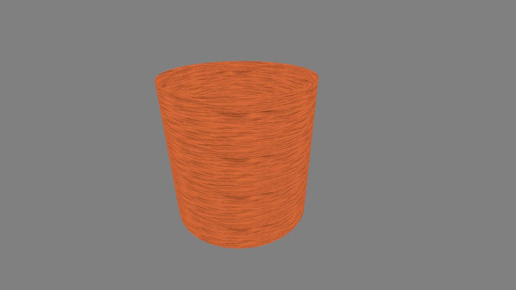
Okay. Let’s put this sucker to work. Here’s how to generate a cylinder.

indexMesh(mesh, 32, 2, function(ar, yr) {

	var x = Math.cos(ar * Math.PI * 2);
	var y = 2 * yr;
	var z = Math.sin(ar * Math.PI * 2);

	mesh.set(x, y, z, ar, yr);

}, false);

We interpret the normalized coordinates as an angle and a y-coordinate, and we transform them appropriately. Note that though we apply 32 steps for the angle, we only need 2 for the y-coordinate, as a cylinder is straight along its length. Vertexes are added to the mesh as they are calculated, plus texture coordinates.

Now, instead of using the second parameter as a y-coordinate, we could interpret it as a second angle, and generate a sphere that way. I’m not going to do that, however. Here’s a first crack at something different.

indexMesh(mesh, 16, 16, function(xr, zr) {

	var x = 2 * (xr - 0.5);
	var z = 2 * (zr - 0.5);
	var y = (1 - x * x) * (1 - z * z);

	mesh.set(x, y, z, xr, zr);

}, true);

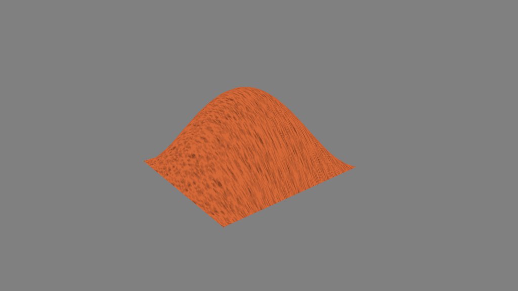
The callback transforms the normalized coordinates from (0..1) to (-1..1), applies a formula to obtain a y-coordinate, then adds that vertex to the mesh.

Hooray, a heightmap. Well, that’s not much use as a sphere, is it? To get over the hump, we introduce an object that should be a part of every 3D toolkit: the vector.

var p = SOAR.vector.create();
indexMesh(mesh, 16, 16, function(xr, zr) {

	p.x = 2 * (xr - 0.5);
	p.z = 2 * (zr - 0.5);
	p.y = (1 - p.x * p.x) * (1 - p.z * p.z);
	p.norm();
	mesh.set(p.x, p.y, p.z, xr, zr);

}, true);

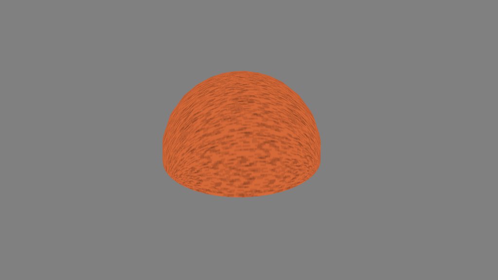
Most of this code does exactly what the last snippet did: transform x and z, find y, and generate a vertex. This snippet, however, places the (x, y, z) point into a vector, and normalizes the vector. The result?

Where’d that come from? Well, all normalized vectors have a length of 1, so they all have the same distance from the origin. Or, to put it another way, they’re equidistant from a central point. Sounds like the definition of a sphere, right?

Wait, that’s only half a sphere. Where’s the other half?

var p = SOAR.vector.create();
function sphere(x, y, z) {
	p.x = 2 * (x - 0.5);
	p.z = 2 * (z - 0.5);
	p.y = (1 - Math.abs(p.x)) * (1 - Math.abs(p.z));
	p.norm();
	mesh.set(p.x, y * p.y, p.z, x, z);
}
indexMesh(mesh, 16, 16, function(xr, zr) {
	sphere(xr, 1, zr);
}, true);

indexMesh(mesh, 16, 16, function(xr, zr) {
	sphere(xr, -1, zr);
}, false);

I’m not a huge fan of code duplication, so I placed the calculation into a separate function. The y parameter of the sphere function determines the sign of the y coordinate and allows us to generate a second half-sphere under the first. Note that the second bit of code has a different winding order.

I’ve glossed over the formula that determines the y-coordinate. I don’t recall how I derived it, but the exact form doesn’t seem to matter. What you need is a function that’ll give you a “hump” in y across the xz plane, dropping to 0 at the edges and rising to 1 at the center. I’ve successfully used (1 – x4) * (1 – z4) and (1 – abs(x)) * (1 – abs(z)).

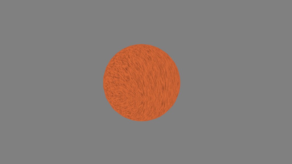
Though this method avoids polar distortion of the texture, it still looks a little weird around the equator, which isn’t helped by the fact that I’m merely reflecting it through the xz plane in this example. One approach I want to try is using the actual vertex positions as texture coordinates, and simulate a 3D texture in the fragment shader. We’ll see what comes of it.

a little patch of grass

You know how it is. Making landscapes out of heightmaps is great, but sooner or later, those rolling hills start looking a little flat. Real hills have grass sticking out of them.

But you can’t model each individual blade of grass without blowing your polygon budget. What do you do?

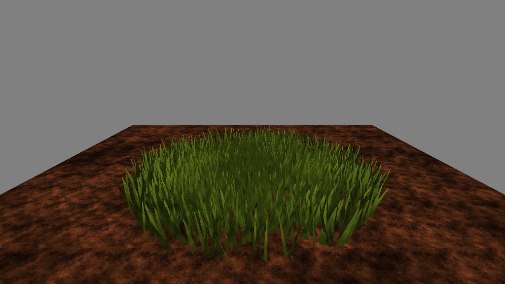
The obvious starting point is alpha blending. Find a side view image of a clump of grass, make it a texture, set the non-grass pixels transparent, and scatter little billboards bearing that texture all over your hillside. Instant grass, right?

Not so fast. Alpha blending requires careful attention to z-order. You have to draw all your billboards in just the right order, or background pixels will wipe out foreground pixels. To make matters worse, the “right order” depends on where the camera is at any given time. You’d have to mantain an octree of mesh objects and draw each separately. Never mind your polygon budget—your CPU budget’s just gone to hell.

Fortunately, the GLSL specification provides a solution: discard. This keyword, if issued as the last line of a fragment shader, forces the GPU to throw away any changes to the current pixel. Both the depth buffer and the color buffer are unaffected. Used with a conditional, discard lets you create “punch-out” regions that you can see through—and drawing order doesn’t affect a thing.

Enough talk. Here’s some code.

var ang, x0, z0, x1, z1;
var i, j, d;
for (ang = 0, i = 0, j = 0; i < 100; i++, j += 4) {
	// pick a starting point for the billboard
	// based on whatever the current angle is
	x0 = Math.cos(ang);
	z0 = Math.sin(ang);
	// pick a new angle that's between pi/2 and 3pi/2 radians
	ang += rng.get(Math.PI * 0.5, Math.PI * 1.5);
	// pick the ending point for the billboard
	x1 = Math.cos(ang);
	z1 = Math.sin(ang);
	// determine the distance between the two points
	// we use this in texture coordinates to prevent
	// longer billboards from stretching the texture
	d = Math.sqrt(Math.pow(x0 - x1, 2) + Math.pow(z0 - z1, 2));

	// set the four points of the quad, bending slightly at the top
	// to create a "bent stalks" effect, and dropping below the dirt
	// so no connecting lines are visible.
	mesh.set(x0, -0.1, z0, 0, 0);
	mesh.set(x0 + rng.get(-0.1, 0.1), 0.25, z0 + rng.get(-0.1, 0.1), 0, 1);

	mesh.set(x1 + rng.get(-0.1, 0.1), 0.25, z1 + rng.get(-0.1, 0.1), d, 1);
	mesh.set(x1, -0.1, z1, d, 0);

	// generate the indicies
	mesh.index(j, j + 1, j + 3, j + 1, j + 2, j + 3);
}

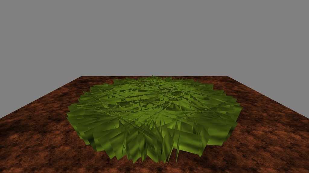
For this demo, I’m creating a circular patch of thick grass, so I pick random points around a circle and draw quads from one point to the next. If I weren’t discarding pixels, the end product would look like this.

You can probably imagine what a mess that would be with alpha-blending. Here’s what we do in the fragment shader instead.

precision mediump float;

const float PI = 3.141592654;

uniform sampler2D stem;

varying vec3 obj;
varying vec3 eye;
varying vec2 tex;

void main(void) {

	// this bit simply generates color and shading for the grass stems,
	// and has nothing at all to do with discarding pixels
	float l = texture2D(stem, tex * 0.01).r * texture2D(stem, tex * 0.1).r * 2.0;
	float c = texture2D(stem, tex * 0.02).r * texture2D(stem, tex * 0.2).r * 3.0;
	vec3 col = l * mix(vec3(0.0, 0.0, 0.0), vec3(0.57, 0.71, 0.14), c);
	gl_FragColor = vec4(col, 1.0);

	// generate a skinny sinewave along the x-axis
	float t = pow(sin(32.0 * tex.x), 8.0);
	// if the sinewave value is less than the y-axis
	// toss the fragment away
	if (t < tex.y)
		discard;
}

It’s actually pretty simple, and if I’d used a grass texture instead of faking it with a sinewave, it would be even simpler. The first chunk of code generates the actual pixel color. Nothing staggering there. The magic happens in the second chunk.

I take advantage of the way I’ve set up the texture coordinates. On the x-axis, texture coordinates run from zero to the length of the billboard, so I can generate a sinewave along that length. I raise the sinewave to an even power to make it skinny and non-negative.

The y-axis runs from zero at the bottom to one at the top. If the sinewave output is smaller than this value, than we discard the pixel value—whatever we’ve set gl_FragCoord to above. No color value is placed in the buffer as a result. Instead of a color, we have a hole we can see through. Sweet.

The practical upshot is that I can generate something that looks like grass, then I can discard anything that isn’t grass. If I were using a grass texture, I could simply toss away anything where the alpha value was less than 0.5. This gives you the “good” effect of alpha blending without the “bad” effects of z-order.

There’s one caveat that I’m aware of. If you create a situation where the camera is looking through many layers of punchouts, the frame rate sinks like a stone. I suspect this has to do with hidden surface removal. The GPU is trying to sort out what looks like a massively complex scene with loads of objects at many different depths. It takes time.

The best solution I’ve found simply avoids the problem: keep the camera from looking through too many holes at once.

Want to see it all in action? Live Demo (WSAD to move, Q for fullscreen.)

full screen gas!

Gas Food Lodging now supports Fullscreen and Pointer Lock! No more dragging and dropping that mouse. Press F at the title prompt to activate the new mode, and see the wonders explode across a slightly larger screen area!

make a drunken noise

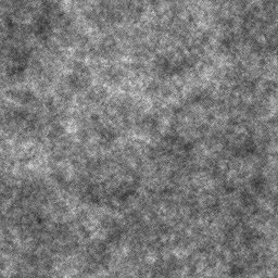
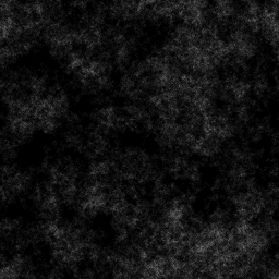
I like a bit of structured noise. Photoshop (and the GIMP) call it difference clouds, but to me it’s always been drunkwalk, because that’s the algorithm I use to make it. For past games, I wrote a C program to iterate random steps across an array and place the results in an image file, like so.

I’d load that image from the server and hand it off to WebGL as a texture, doing a little Perlinization in the fragment shader to colorize and stretch it. However, what I really wanted was client-side generation. I wanted to make them on the fly and use them for a load of other purposes. Heightmaps, for example. There’s a smoothness to drunkwalk noise that just pulling random numbers out of the air doesn’t get you. You’ve got to add that stuff up.

So I finally added a drunkwalk noise generator to my toolkit.

walk: function (img, seed, reps, blend, c, p0, p1, p2, p3) {
	var w = img.width;
	var h = img.height;
	var il = Math.round(w * h * reps);
	var rng = this.rng;
	var dt = img.data;
	var dnelb = 1 - blend;
	var x, y, i, j;

	rng.reseed(seed);
	x = Math.floor(rng.get(0, w));
	y = Math.floor(rng.get(0, h));
	for (i = 0; i < il; i++) {
		j = x + w * y;
		dt[j] = Math.round(dt[j] * dnelb + c * blend);

		if (rng.get() < p0) {
 			x++;
 			if (x >= w) {
				x = 0;
			}
		}
		if (rng.get() < p1) {
 			y++;
 			if (y >= h) {
				y = 0;
			}
		}
		if (rng.get() < p2) {
			x--;
			if (x < 0) {
				x = w - 1;
			}
		}
		if (rng.get() < p3) {
			y--;
			if (y < 0) {
				y = h - 1;
			}
		}
	}
}

To generate a typical chunk of structured noise, you’d pass parameters like this.

walk(tex, seed, 8, 0.02, 255, 0.5, 0.5, 0.5, 0.5);

We assume the tex object resembles a native ImageData object in having height, width, and data properties. However, the data format is a single byte luminance channel (as opposed to the four-byte RGBA format). You can still pass this right into WebGL as a texture, and colorize it in the shader.

You can pass a custom seed, which will generate the same pattern each time, or a zero to select a random pattern. (The rng object is a static RNG handing out numbers from zero to one.)

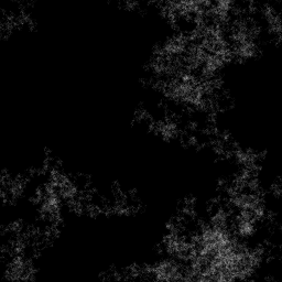
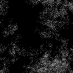
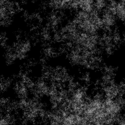
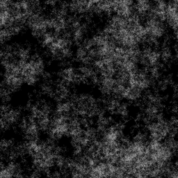
The reps parameter is the most important. Good patterns require a large number of steps, and the larger the size of the array, the more steps you need. Thus, I specify the number of steps as a multiple of the area.

reps = 2

reps = 4

reps = 6

reps = 8

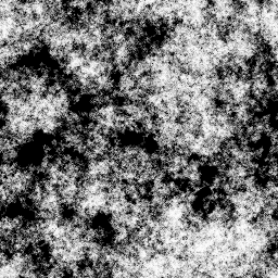
The blend parameter works like an alpha-blending value, determining how much each step will blend between the intensity present in the channel and the intensity given by the c parameter. In this case, I’m blending between 0 and 255.

blend = 0.01

blend = 0.1

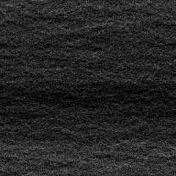
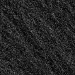
The p0-p3 values let you alter the probability that your “drunk” will stumble in one direction or another on each step. Changing the probabilities alters the structure of the resulting image.

p = (0.1, 0.5, 0.5, 0.5)

p = (0.35, 0.67, 0.5, 0.5)

p = ( 0, 0.5, 0.65, 0.9)

Performance isn’t bad, thanks to JIT compilation. I can generate about ten 64×64 images (with a reps value of 8) without noticing any slowdown on a 2GHz AMD64.

You may note that the algorithm enforces boundary conditions in an odd way. If a step takes us off the “side” of the array (i.e., x > width), we resume on the opposite side (x == 0). This creates a natural tiling effect that makes texturing a breeze.