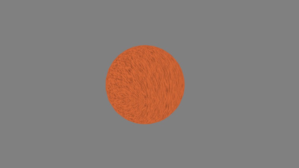
Sooner or later, every student of 3D graphics winds up drawing a sphere. It’s one of the canonical constructs of geometry—a set of points equidistant from a central point—and one of the most important shapes in the physical world.
It’s also a source of frustration. Most first-timers wind up with a tangle of cosines, and a hard lesson in the fundamental problem of cartography.
Oops. The right way to generate a sphere is to subdivide a polyhedron. However, I’ve come up with another method. Is it the right way? The wrong way? The Max Power way? You decide.
Let me start by introducing a simple helper function. Often, I’ll want to generate a “sheet” of vertexes that I can deform and transform one by one. The classic example is a heightmap, where I iterate over the x and z coordinates to adjust y coordinates. I want a simple callback that lets me set each vertex and handles the details for me.
/**
	iterate over a 2D mesh with indexing

	@method indexMesh
	@param mesh object
	@param il number, steps for first dimension
	@param jl number, steps for second dimension
	@param func function, callback to generate point field
	@param wind boolean, winding order
**/

indexMesh: function(mesh, il, jl, func, wind) {
	var im = il - 1;
	var jm = jl - 1;
	var k = mesh.length / mesh.stride;
	var i, j;

	for (i = 0; i < il; i++) {
		for (j = 0; j < jl; j++, k++) {
			func(i / im, j / jm);
			if (i < im && j < jm) {
				if (wind) {
					mesh.index(k, k + jl, k + 1, k + jl, k + jl + 1, k + 1);
				} else {
					mesh.index(k, k + 1, k + jl, k + jl, k + 1, k + jl + 1);
				}
			}
		}
	}
}
The mesh object referenced here is the one from my own toolkit, but the concept should translate to others. We determine a starting index k by dividing the current length of the mesh by its stride, which tells us how many vertexes the mesh contains. Iterating over two arbitrary dimensions, we call into a user-supplied function on each inner loop. I pass “normalized” coordinates (values between 0 and 1) to that function.
The idea, of course, is that il and jl determine the resolution of the resulting mesh. Each represents a number of steps across an arbitrary dimension. The callback can perform any transform on the normalized coordinates to make them into whatever coordinates are necessary. It’s handy. The remainder of the code generates indexes for the mesh according to the winding order the user specifies with the wind parameter.
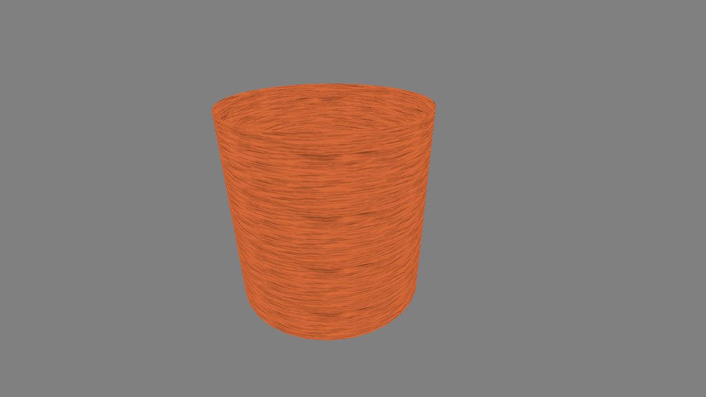
Okay. Let’s put this sucker to work. Here’s how to generate a cylinder.
indexMesh(mesh, 32, 2, function(ar, yr) {

	var x = Math.cos(ar * Math.PI * 2);
	var y = 2 * yr;
	var z = Math.sin(ar * Math.PI * 2);

	mesh.set(x, y, z, ar, yr);

}, false);
We interpret the normalized coordinates as an angle and a y-coordinate, and we transform them appropriately. Note that though we apply 32 steps for the angle, we only need 2 for the y-coordinate, as a cylinder is straight along its length. Vertexes are added to the mesh as they are calculated, plus texture coordinates.
Now, instead of using the second parameter as a y-coordinate, we could interpret it as a second angle, and generate a sphere that way. I’m not going to do that, however. Here’s a first crack at something different.
indexMesh(mesh, 16, 16, function(xr, zr) {

	var x = 2 * (xr - 0.5);
	var z = 2 * (zr - 0.5);
	var y = (1 - x * x) * (1 - z * z);

	mesh.set(x, y, z, xr, zr);

}, true);
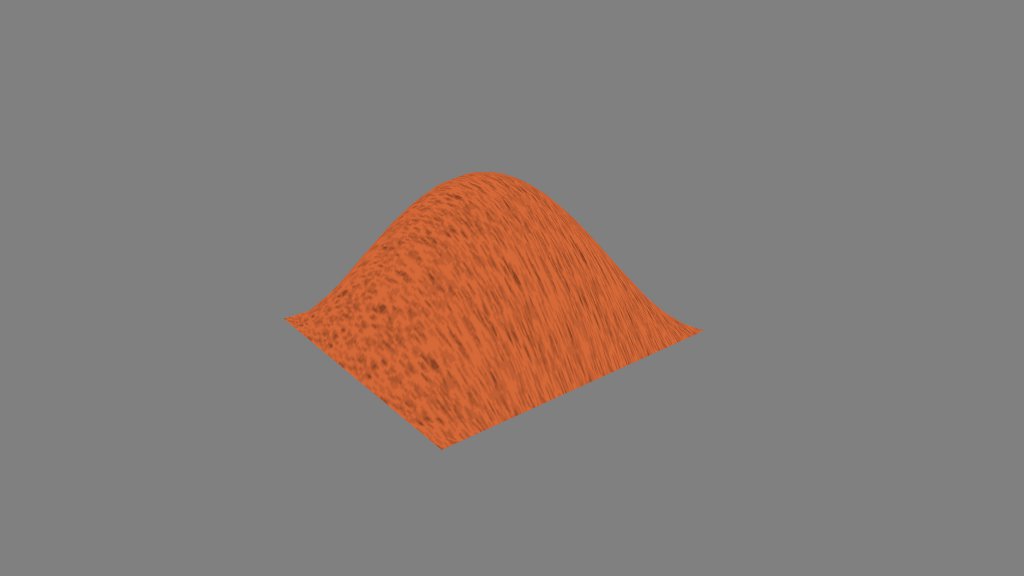
The callback transforms the normalized coordinates from (0..1) to (-1..1), applies a formula to obtain a y-coordinate, then adds that vertex to the mesh.
Hooray, a heightmap. Well, that’s not much use as a sphere, is it? To get over the hump, we introduce an object that should be a part of every 3D toolkit: the vector.
var p = SOAR.vector.create();
indexMesh(mesh, 16, 16, function(xr, zr) {

	p.x = 2 * (xr - 0.5);
	p.z = 2 * (zr - 0.5);
	p.y = (1 - p.x * p.x) * (1 - p.z * p.z);
	p.norm();
	mesh.set(p.x, p.y, p.z, xr, zr);

}, true);
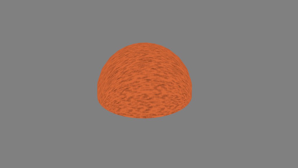
Most of this code does exactly what the last snippet did: transform x and z, find y, and generate a vertex. This snippet, however, places the (x, y, z) point into a vector, and normalizes the vector. The result?
Where’d that come from? Well, all normalized vectors have a length of 1, so they all have the same distance from the origin. Or, to put it another way, they’re equidistant from a central point. Sounds like the definition of a sphere, right?
Wait, that’s only half a sphere. Where’s the other half?
var p = SOAR.vector.create();
function sphere(x, y, z) {
	p.x = 2 * (x - 0.5);
	p.z = 2 * (z - 0.5);
	p.y = (1 - Math.abs(p.x)) * (1 - Math.abs(p.z));
	p.norm();
	mesh.set(p.x, y * p.y, p.z, x, z);
}
indexMesh(mesh, 16, 16, function(xr, zr) {
	sphere(xr, 1, zr);
}, true);

indexMesh(mesh, 16, 16, function(xr, zr) {
	sphere(xr, -1, zr);
}, false);
I’m not a huge fan of code duplication, so I placed the calculation into a separate function. The y parameter of the sphere function determines the sign of the y coordinate and allows us to generate a second half-sphere under the first. Note that the second bit of code has a different winding order.
I’ve glossed over the formula that determines the y-coordinate. I don’t recall how I derived it, but the exact form doesn’t seem to matter. What you need is a function that’ll give you a “hump” in y across the xz plane, dropping to 0 at the edges and rising to 1 at the center. I’ve successfully used (1 – x4) * (1 – z4) and (1 – abs(x)) * (1 – abs(z)).
Though this method avoids polar distortion of the texture, it still looks a little weird around the equator, which isn’t helped by the fact that I’m merely reflecting it through the xz plane in this example. One approach I want to try is using the actual vertex positions as texture coordinates, and simulate a 3D texture in the fragment shader. We’ll see what comes of it.
