march of the cubes

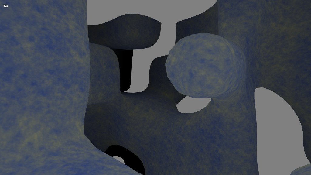
My last post got me onto the subject of 3D textures. In the process of researching the topic, I decided I needed better models to texture. Spheres are cool and all, but I’ll take a 3D noise function any day. It was time to dive into the marching cubes algorithm.

The principle is pretty simple. Take a scalar field—that is, a function that assigns a number to every point in space—and set a threshold value. You now have an isosurface. Every point assigned a number less than that threshold is inside the surface, and every point assigned a greater number is outside.

It’s like a contour plot, except as it’s in three dimensions, it’s a surface rather than a line. The marching cubes algorithm generates the polygons that make up that surface. Neat!

I won’t go into the details of the algorithm itself. It’s fairly well documented at Paul Bourke’s site, where I found the C code to port to Javascript. Instead, I’ll just document a few things I worked out while testing it.

Sadly, I still don’t have a true solution to the 3D texture problem. I tried generating Perlin noise in the shader, using a function like

sin(big-number1 * x) * sin(big-number2 * y) * sin(big-number3 * z)

as a noise source and interpolating across integer boundaries. The results weren’t bad, visually speaking, but my implementation was simply too slow for comfort. Each texture fragment requires eight noise samples and seven interpolations, and with several layers making up each texture surface my midrange video card was dropping frames like mad. Either a hardware noise source or a native GLSL trilinear interpolation instruction would have saved the day. (For that matter, native WebGL support for 3D textures would have helped a bit.)

I also tried Perlin’s more recent simplex noise algorithm, but had the same issues with performance. There appear to be other possible implementations out there, so I may revisit this one.

Ultimately, I applied the solution used in the WebGL Caves demo (which also has a nice marching cubes implementation). We can simulate a 3D texture with a weighted sum of three 2D textures, each tied to a specific plane (xy, yz, and xz). The normals to the surface points are used as weighting factors.

//
// vertex shader
// note assignment of normals to texture coordinates
//

attribute vec3 position;
attribute vec3 normal;

uniform mat4 projector;
uniform mat4 modelview;

varying vec3 obj;
varying vec3 eye;
varying vec3 tex;

void main(void) {
	vec4 pos = modelview * vec4(position, 1.0);
	gl_Position = projector * pos;
	eye = pos.xyz;
	obj = position;
	tex = abs(normal);
}

//
// fragment shader
// normal components used to blend planar contributions
//

precision mediump float;

uniform sampler2D noise;

varying vec3 obj;
varying vec3 eye;
varying vec3 tex;

void main(void) {

	float c0 = tex.z * texture2D(noise, obj.xy).r + tex.x * texture2D(noise, obj.yz).r + tex.y * texture2D(noise, obj.xz).r;
	float c1 = tex.z * texture2D(noise, 2.0 * obj.xy).r + tex.x * texture2D(noise, 2.0 * obj.yz).r + tex.y * texture2D(noise, 2.0 * obj.xz).r;

	vec3 col = mix(vec3(0.12, 0.22, 0.57), vec3(0.91, 0.83, 0.27), (c0 + c1) * 0.25);

	float l = (10.0 - length(eye)) / 10.0;
	col = col * l;

	gl_FragColor = vec4(col, 1.0);
}

This produces what looks like a continuous texture across the surface, and no one’s the wiser.

Generating the normal vectors across an arbitrary surface can be a chore. Since I had a scalar field function representing the surface, I was able to do it this way.

var n = SOAR.vector.create();

// generates surface from 3D noise function
var noise = SOAR.noise3D.create(1968103401, 1, 32, 0.5);
var field = this.field = function(x, y, z) {
	return noise.get(x, y, z);
};

// generates surface normals for texture blending
// (really a gradient function, but as it points 
// toward wherever the field is strongest, it will
// always point *away* from the local isosurface)
var gradient = this.gradient = function(n, x, y, z) {
	n.x = field(x + step, y, z) - field(x - step, y, z);
	n.y = field(x, y + step, z) - field(x, y - step, z);
	n.z = field(x, y, z + step) - field(x, y, z - step);
	n.norm();
};

I sample the field at the opposite corners of a cube, take the difference, normalize the results, and boo-ya! Instant surface normal. (Or gradient. Not sure it matters, if it works.)

The initial meshes I generated were uncomfortably large. I needed a way to index the mesh, and I couldn’t make any assumptions about the ordering of the vertexes. So, I decided to apply the simplest solution I could think of: store off each vertex, assign it an an index, then apply the index when the vertex is referenced again.

var hash = {};
var indx = 0;

// callback for building surface mesh
function polycb(p) {
	gradient(n, p.x, p.y, p.z);
	var key = Math.floor(p.x * 100) + "." + Math.floor(p.y * 100) + "." + Math.floor(p.z * 100);
	var ent = hash[key];
	if (ent !== undefined) {
		mesh.index(ent);
	} else {
		mesh.set(p.x, p.y, p.z, n.x, n.y, n.z);
		mesh.index(indx);
		hash[key] = indx++;
	}
}

This was my first attempt at using a JavaScript associative array to store a large number of keys. I liked its simplicity and performance—it added about 15% to the run time, while cutting the vertex count by a factor of six.

Note that the keys are generated by concatenating scaled integer coordinates. I’d initially used the floating point coordinates, but due to JavaScript’s issues representing decimal numbers, the resulting keys were nearly 30 characters long and took forever to look up. Scaling and truncating the coordinates brought keys down to 6-9 characters, and provided much faster lookup times.

Once I could generate these complex surfaces, I wanted to fly about inside them. I needed a way to detect collisions between the camera and the surface.

// set up the camera direction vector
direct.set(0, 0, 0);
if (motion.movefore) {
	direct.add(camera.front);
}
if (motion.moveback) {
	direct.sub(camera.front);
}
if (motion.moveleft) {
	direct.sub(camera.right);
}
if (motion.moveright) {
	direct.add(camera.right);
}
speed = (motion.movefast ? 2 : 1) * SOAR.sinterval;
direct.norm();

// find the camera's next position given the current travel direction
tempps.copy(direct).mul(speed).add(pos);
// check the field value at that position; is it less than the cutoff?
if (BED.mctest.field(tempps.x, tempps.y, tempps.z) < 0.51) {
	// get the normal vector near the surface
	tempps.add(pos).mul(0.5);
	BED.mctest.gradient(normal, tempps.x, tempps.y, tempps.z);
	// adding normal to player direction should push us away
	direct.add(normal);
	// however, the vector sum tends to jitter when we're
	// pointed toward the surface so check the dot product
	if (direct.dot(normal) < 1) {
		// rotating sum around the normal smoothes it a bit
		direct.cross(normal).neg().cross(normal);
	}
}

direct.mul(speed);
pos.add(direct);

Again, a scalar field function comes in handy. As the surface exists wherever the field’s value is 0.5, I use 0.51 as the collision cutoff. (Setting the cutoff to 0.5 would allow the camera to penetrate the surface.) When I have a field function, I like to handle collisions by taking the vector sum of the camera’s direction and the normal at the collision point. I can add the resulting vector to the camera’s position, which prevents it from moving any closer to the surface.

In this case, motion across the surface caused the camera to jitter as the normal changed, and I had to find a way to stablilize it. Though I’m not certain why, rotating the vector sum around the normal smooths it out.

To see it all in action, go to the Live Demo. WSAD steers. Hit Q for fullscreen.

the index of the spheres

Sooner or later, every student of 3D graphics winds up drawing a sphere. It’s one of the canonical constructs of geometry—a set of points equidistant from a central point—and one of the most important shapes in the physical world.

It’s also a source of frustration. Most first-timers wind up with a tangle of cosines, and a hard lesson in the fundamental problem of cartography.

Oops. The right way to generate a sphere is to subdivide a polyhedron. However, I’ve come up with another method. Is it the right way? The wrong way? The Max Power way? You decide.

Let me start by introducing a simple helper function. Often, I’ll want to generate a “sheet” of vertexes that I can deform and transform one by one. The classic example is a heightmap, where I iterate over the x and z coordinates to adjust y coordinates. I want a simple callback that lets me set each vertex and handles the details for me.

/**
	iterate over a 2D mesh with indexing

	@method indexMesh
	@param mesh object
	@param il number, steps for first dimension
	@param jl number, steps for second dimension
	@param func function, callback to generate point field
	@param wind boolean, winding order
**/

indexMesh: function(mesh, il, jl, func, wind) {
	var im = il - 1;
	var jm = jl - 1;
	var k = mesh.length / mesh.stride;
	var i, j;

	for (i = 0; i < il; i++) {
		for (j = 0; j < jl; j++, k++) {
			func(i / im, j / jm);
			if (i < im && j < jm) {
				if (wind) {
					mesh.index(k, k + jl, k + 1, k + jl, k + jl + 1, k + 1);
				} else {
					mesh.index(k, k + 1, k + jl, k + jl, k + 1, k + jl + 1);
				}
			}
		}
	}
}

The mesh object referenced here is the one from my own toolkit, but the concept should translate to others. We determine a starting index k by dividing the current length of the mesh by its stride, which tells us how many vertexes the mesh contains. Iterating over two arbitrary dimensions, we call into a user-supplied function on each inner loop. I pass “normalized” coordinates (values between 0 and 1) to that function.

The idea, of course, is that il and jl determine the resolution of the resulting mesh. Each represents a number of steps across an arbitrary dimension. The callback can perform any transform on the normalized coordinates to make them into whatever coordinates are necessary. It’s handy. The remainder of the code generates indexes for the mesh according to the winding order the user specifies with the wind parameter.

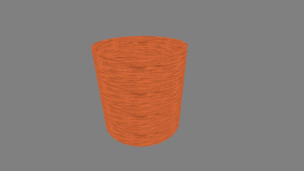
Okay. Let’s put this sucker to work. Here’s how to generate a cylinder.

indexMesh(mesh, 32, 2, function(ar, yr) {

	var x = Math.cos(ar * Math.PI * 2);
	var y = 2 * yr;
	var z = Math.sin(ar * Math.PI * 2);

	mesh.set(x, y, z, ar, yr);

}, false);

We interpret the normalized coordinates as an angle and a y-coordinate, and we transform them appropriately. Note that though we apply 32 steps for the angle, we only need 2 for the y-coordinate, as a cylinder is straight along its length. Vertexes are added to the mesh as they are calculated, plus texture coordinates.

Now, instead of using the second parameter as a y-coordinate, we could interpret it as a second angle, and generate a sphere that way. I’m not going to do that, however. Here’s a first crack at something different.

indexMesh(mesh, 16, 16, function(xr, zr) {

	var x = 2 * (xr - 0.5);
	var z = 2 * (zr - 0.5);
	var y = (1 - x * x) * (1 - z * z);

	mesh.set(x, y, z, xr, zr);

}, true);

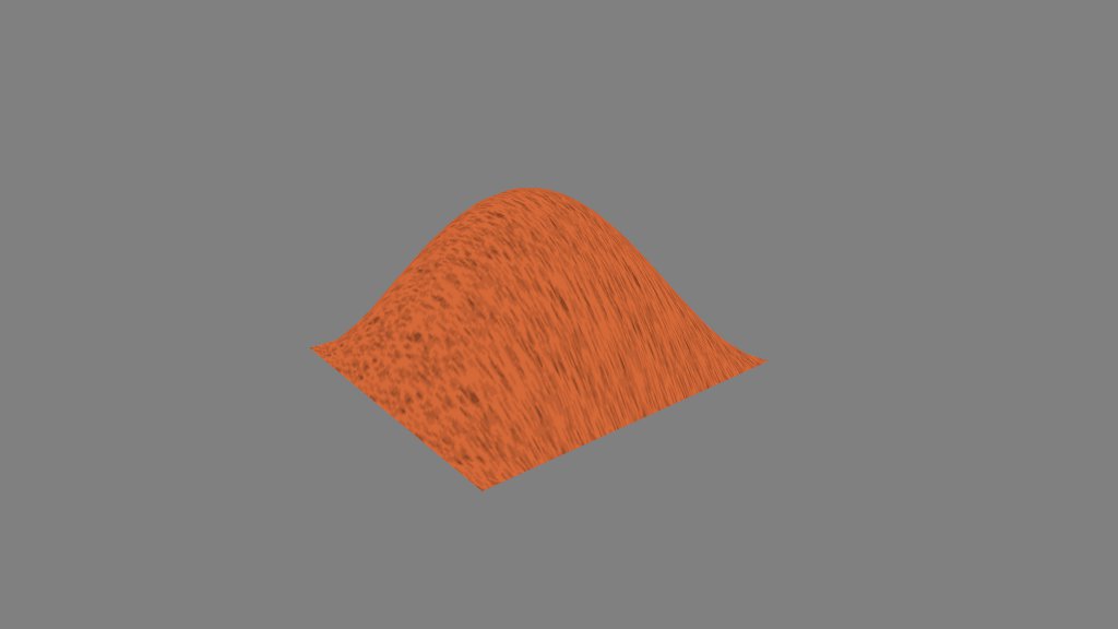
The callback transforms the normalized coordinates from (0..1) to (-1..1), applies a formula to obtain a y-coordinate, then adds that vertex to the mesh.

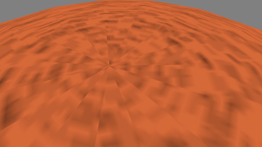
Hooray, a heightmap. Well, that’s not much use as a sphere, is it? To get over the hump, we introduce an object that should be a part of every 3D toolkit: the vector.

var p = SOAR.vector.create();
indexMesh(mesh, 16, 16, function(xr, zr) {

	p.x = 2 * (xr - 0.5);
	p.z = 2 * (zr - 0.5);
	p.y = (1 - p.x * p.x) * (1 - p.z * p.z);
	p.norm();
	mesh.set(p.x, p.y, p.z, xr, zr);

}, true);

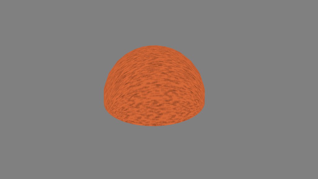
Most of this code does exactly what the last snippet did: transform x and z, find y, and generate a vertex. This snippet, however, places the (x, y, z) point into a vector, and normalizes the vector. The result?

Where’d that come from? Well, all normalized vectors have a length of 1, so they all have the same distance from the origin. Or, to put it another way, they’re equidistant from a central point. Sounds like the definition of a sphere, right?

Wait, that’s only half a sphere. Where’s the other half?

var p = SOAR.vector.create();
function sphere(x, y, z) {
	p.x = 2 * (x - 0.5);
	p.z = 2 * (z - 0.5);
	p.y = (1 - Math.abs(p.x)) * (1 - Math.abs(p.z));
	p.norm();
	mesh.set(p.x, y * p.y, p.z, x, z);
}
indexMesh(mesh, 16, 16, function(xr, zr) {
	sphere(xr, 1, zr);
}, true);

indexMesh(mesh, 16, 16, function(xr, zr) {
	sphere(xr, -1, zr);
}, false);

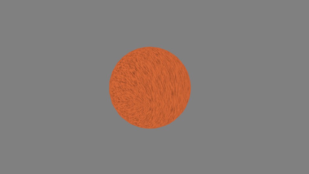
I’m not a huge fan of code duplication, so I placed the calculation into a separate function. The y parameter of the sphere function determines the sign of the y coordinate and allows us to generate a second half-sphere under the first. Note that the second bit of code has a different winding order.

I’ve glossed over the formula that determines the y-coordinate. I don’t recall how I derived it, but the exact form doesn’t seem to matter. What you need is a function that’ll give you a “hump” in y across the xz plane, dropping to 0 at the edges and rising to 1 at the center. I’ve successfully used (1 – x4) * (1 – z4) and (1 – abs(x)) * (1 – abs(z)).

Though this method avoids polar distortion of the texture, it still looks a little weird around the equator, which isn’t helped by the fact that I’m merely reflecting it through the xz plane in this example. One approach I want to try is using the actual vertex positions as texture coordinates, and simulate a 3D texture in the fragment shader. We’ll see what comes of it.

a little patch of grass

You know how it is. Making landscapes out of heightmaps is great, but sooner or later, those rolling hills start looking a little flat. Real hills have grass sticking out of them.

But you can’t model each individual blade of grass without blowing your polygon budget. What do you do?

The obvious starting point is alpha blending. Find a side view image of a clump of grass, make it a texture, set the non-grass pixels transparent, and scatter little billboards bearing that texture all over your hillside. Instant grass, right?

Not so fast. Alpha blending requires careful attention to z-order. You have to draw all your billboards in just the right order, or background pixels will wipe out foreground pixels. To make matters worse, the “right order” depends on where the camera is at any given time. You’d have to mantain an octree of mesh objects and draw each separately. Never mind your polygon budget—your CPU budget’s just gone to hell.

Fortunately, the GLSL specification provides a solution: discard. This keyword, if issued as the last line of a fragment shader, forces the GPU to throw away any changes to the current pixel. Both the depth buffer and the color buffer are unaffected. Used with a conditional, discard lets you create “punch-out” regions that you can see through—and drawing order doesn’t affect a thing.

Enough talk. Here’s some code.

var ang, x0, z0, x1, z1;
var i, j, d;
for (ang = 0, i = 0, j = 0; i < 100; i++, j += 4) {
	// pick a starting point for the billboard
	// based on whatever the current angle is
	x0 = Math.cos(ang);
	z0 = Math.sin(ang);
	// pick a new angle that's between pi/2 and 3pi/2 radians
	ang += rng.get(Math.PI * 0.5, Math.PI * 1.5);
	// pick the ending point for the billboard
	x1 = Math.cos(ang);
	z1 = Math.sin(ang);
	// determine the distance between the two points
	// we use this in texture coordinates to prevent
	// longer billboards from stretching the texture
	d = Math.sqrt(Math.pow(x0 - x1, 2) + Math.pow(z0 - z1, 2));

	// set the four points of the quad, bending slightly at the top
	// to create a "bent stalks" effect, and dropping below the dirt
	// so no connecting lines are visible.
	mesh.set(x0, -0.1, z0, 0, 0);
	mesh.set(x0 + rng.get(-0.1, 0.1), 0.25, z0 + rng.get(-0.1, 0.1), 0, 1);

	mesh.set(x1 + rng.get(-0.1, 0.1), 0.25, z1 + rng.get(-0.1, 0.1), d, 1);
	mesh.set(x1, -0.1, z1, d, 0);

	// generate the indicies
	mesh.index(j, j + 1, j + 3, j + 1, j + 2, j + 3);
}

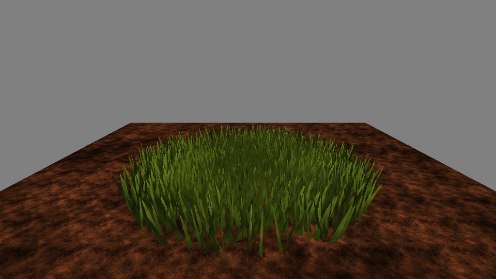
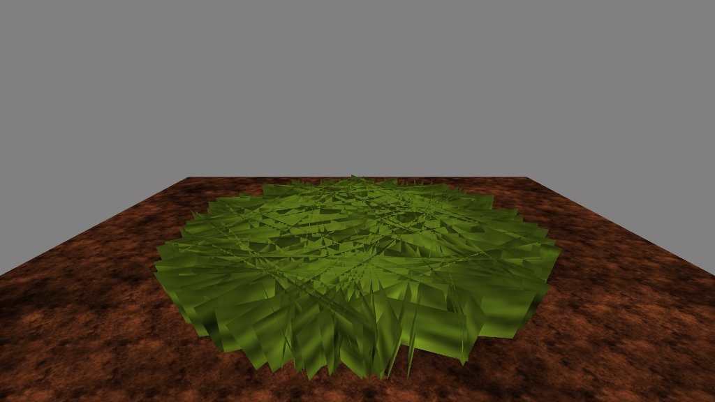
For this demo, I’m creating a circular patch of thick grass, so I pick random points around a circle and draw quads from one point to the next. If I weren’t discarding pixels, the end product would look like this.

You can probably imagine what a mess that would be with alpha-blending. Here’s what we do in the fragment shader instead.

precision mediump float;

const float PI = 3.141592654;

uniform sampler2D stem;

varying vec3 obj;
varying vec3 eye;
varying vec2 tex;

void main(void) {

	// this bit simply generates color and shading for the grass stems,
	// and has nothing at all to do with discarding pixels
	float l = texture2D(stem, tex * 0.01).r * texture2D(stem, tex * 0.1).r * 2.0;
	float c = texture2D(stem, tex * 0.02).r * texture2D(stem, tex * 0.2).r * 3.0;
	vec3 col = l * mix(vec3(0.0, 0.0, 0.0), vec3(0.57, 0.71, 0.14), c);
	gl_FragColor = vec4(col, 1.0);

	// generate a skinny sinewave along the x-axis
	float t = pow(sin(32.0 * tex.x), 8.0);
	// if the sinewave value is less than the y-axis
	// toss the fragment away
	if (t < tex.y)
		discard;
}

It’s actually pretty simple, and if I’d used a grass texture instead of faking it with a sinewave, it would be even simpler. The first chunk of code generates the actual pixel color. Nothing staggering there. The magic happens in the second chunk.

I take advantage of the way I’ve set up the texture coordinates. On the x-axis, texture coordinates run from zero to the length of the billboard, so I can generate a sinewave along that length. I raise the sinewave to an even power to make it skinny and non-negative.

The y-axis runs from zero at the bottom to one at the top. If the sinewave output is smaller than this value, than we discard the pixel value—whatever we’ve set gl_FragCoord to above. No color value is placed in the buffer as a result. Instead of a color, we have a hole we can see through. Sweet.

The practical upshot is that I can generate something that looks like grass, then I can discard anything that isn’t grass. If I were using a grass texture, I could simply toss away anything where the alpha value was less than 0.5. This gives you the “good” effect of alpha blending without the “bad” effects of z-order.

There’s one caveat that I’m aware of. If you create a situation where the camera is looking through many layers of punchouts, the frame rate sinks like a stone. I suspect this has to do with hidden surface removal. The GPU is trying to sort out what looks like a massively complex scene with loads of objects at many different depths. It takes time.

The best solution I’ve found simply avoids the problem: keep the camera from looking through too many holes at once.

Want to see it all in action? Live Demo (WSAD to move, Q for fullscreen.)