Generating procedural graphics on a mobile device requires compromise, cutting corners, and a little cheating. Resources are scarce. Specs are limited. You’re creating content in an environment intended for consuming it.
Sound familiar? Trying to develop real-time 3D games in a browser prepared me for some of these challenges, but the Android platform tossed me a few new ones. Most so far have to do with the fine art of texturing a surface.
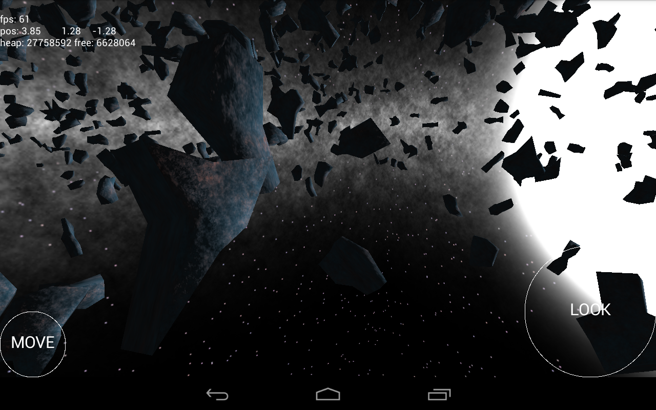
Let’s say I want to generate a landscape: some ground under my (virtual) feet, a few rocks here and there. Using the marching cubes algorithm, I generate a couple of meshes.
Applying texture coordinates to an arbitrary surface isn’t an easy problem. In fact, my research turns up no exact solution. One practical solution uses the components of the normal vector to blend the contributions of each texture plane.
/** vertex shader **/

attribute vec3 position;
attribute vec3 normal;

uniform mat4 projector;
uniform mat4 modelview;

varying vec3 con;
varying vec3 tex;

void main(void) {
	vec4 pos = modelview * vec4(position, 1.0);
	gl_Position = projector * pos;
	tex = position;
	con = abs(normal);
}

/** fragment shader **/

precision mediump float;

uniform sampler2D texture;

varying vec3 con;
varying vec3 tex;

void main(void) {
	gl_FragColor = con.z * texture2D(texture, tex.xy) + con.x * texture2D(texture, tex.yz) + con.y * texture2D(texture, tex.xz);
}
Note the use of the absolute position as texture coordinates. This works without a problem on your average desktop GPU. On mobile hardware, however, things break.
What’s that about? Well, the OpenGL spec defines the minimum levels of floating point precision that a GPU must support: lowp, mediump, and highp. Vertex shaders are required to support up to highp, and fragment shaders…aren’t. A desktop GPU has few power constraints and can get away with using higher-precision numbers everywhere.
My Google Nexus 7 tablet uses the Tegra 3 SoC. It defines two types of precision in a fragment shader: fp20 and fx10. The first maps to mediump and is the highest level available. The fp20 format has one sign bit, six bits for the exponent, and all of thirteen bits for the mantissa, giving it a precision of 2^-13, around 0.0001. Any smaller number is going to be rounded off.
A 256×256-sized texture requires a precision of 1 / 256, around 0.001, to render all of its detail. This isn’t a problem, right? We’ve got one order of magnitude more than we need.
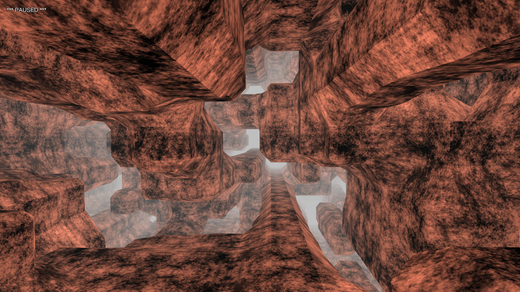
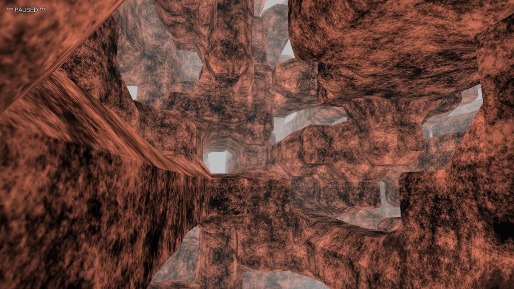
Well, that’s true as long as we stick to normal UV coordinates between [-1, 1]. But if we use absolute position coordinates, as in the planar blending method above, it’s not long before our coordinates are out of that range. Once the coordinates start going over 10, we’re using more and more of our limited precision to store the integer component at the expense of the fractional component, which is rounded off.
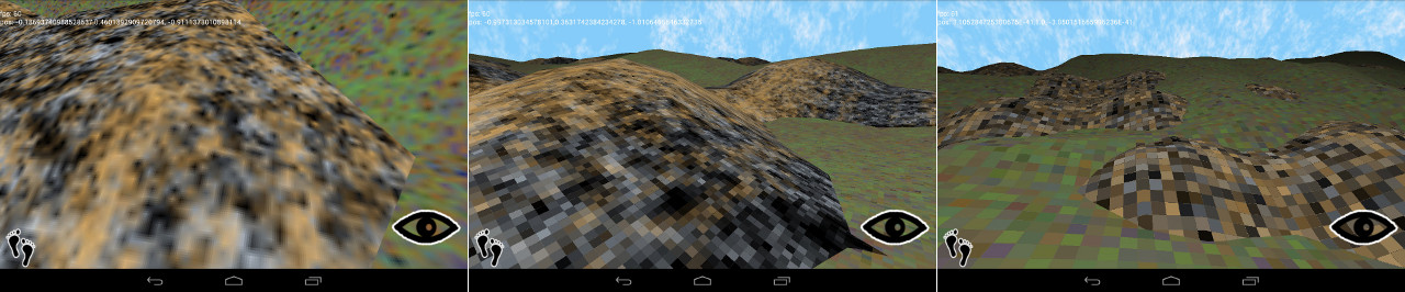
increasing pixelization at z= 10, 100, and 1000
Yuck. Why not use just the fractional component?
/** vertex shader **/

attribute vec3 position;
attribute vec3 normal;

uniform mat4 projector;
uniform mat4 modelview;

varying vec3 con;
varying vec3 tex;

void main(void) {
	vec4 pos = modelview * vec4(position, 1.0);
	gl_Position = projector * pos;
	tex = fract(position);
	con = abs(normal);
}
Yeah, that should work.
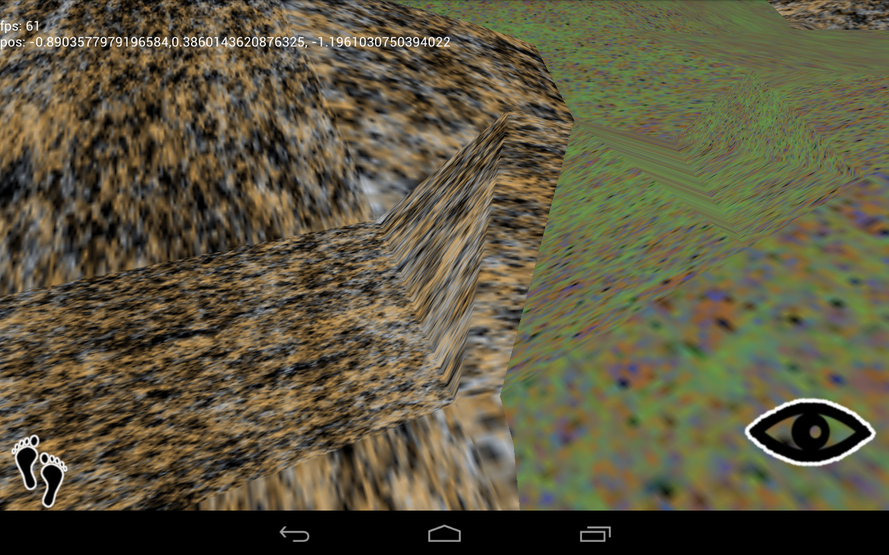
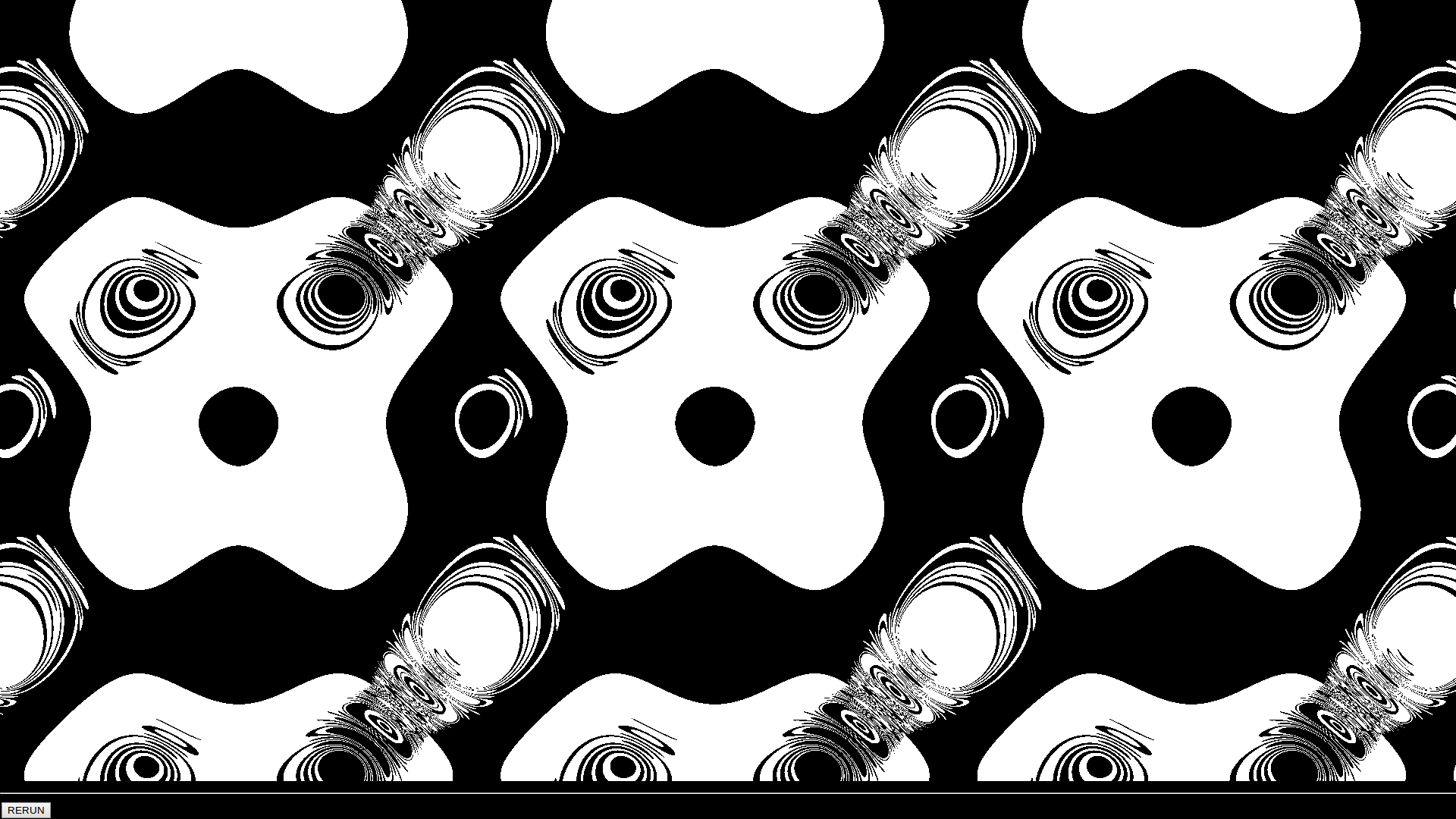
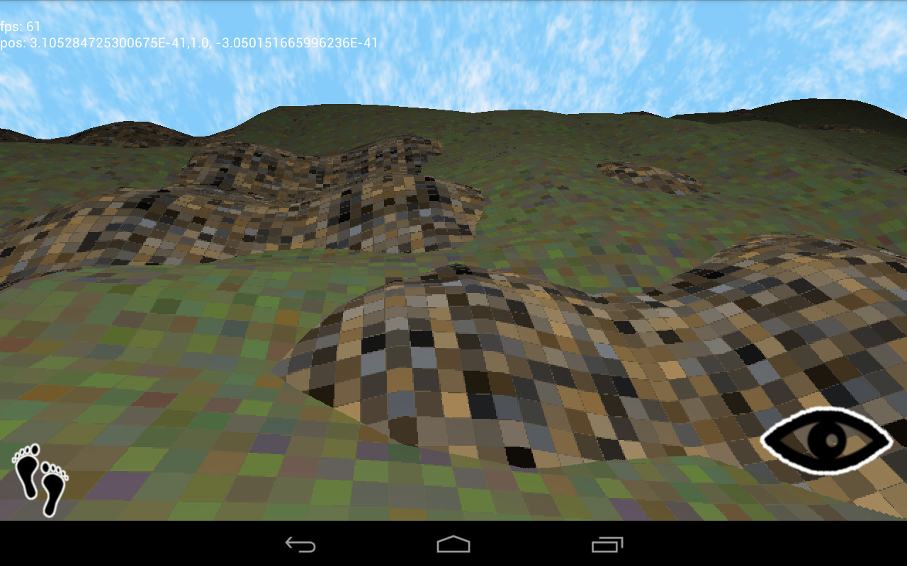
Oops. See, the absolute position preserves the continuity of the surface. Across a mesh, there are many polygons that cross texture boundaries. One triangle might have an x-coordinate of 10.2 on one vertex and 11.3 on the next, a distance of 1.1. Take only the fractional component, and you have 0.2 and 0.3, a distance of 0.1, which stretches the texture between those vertexes, distorting the scene.
Is there a better solution? Sort of. The problem arises because the fract() function is discontinuous across integer boundaries. Let’s eliminate that discontinuity.
/** vertex shader **/

attribute vec3 position;
attribute vec3 normal;

uniform mat4 projector;
uniform mat4 modelview;

varying vec3 con;
varying vec3 tex;

void main(void) {
	vec4 pos = modelview * vec4(position, 1.0);
	gl_Position = projector * pos;
	tex = abs(mod(position, 10.0) - 5.0);
	con = abs(normal);
}
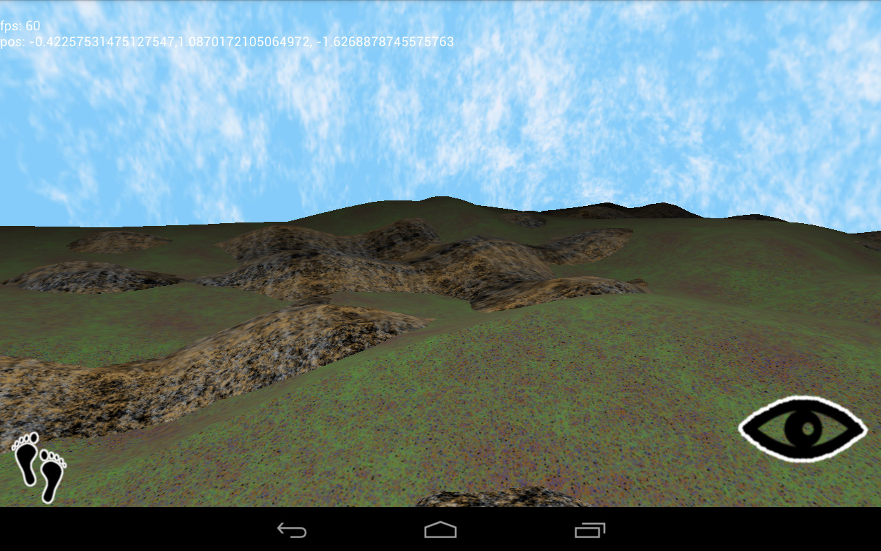
Now, we transform the absolute position into a triangle wave that slopes linearly between [0, 5]. Because there is no discontinuity, the relative distance between vertexes is preserved, and as the texture coordinate never rises above 5, we never lose enough floating point precision to drop texture information.
Is there a catch? Well, naturally.
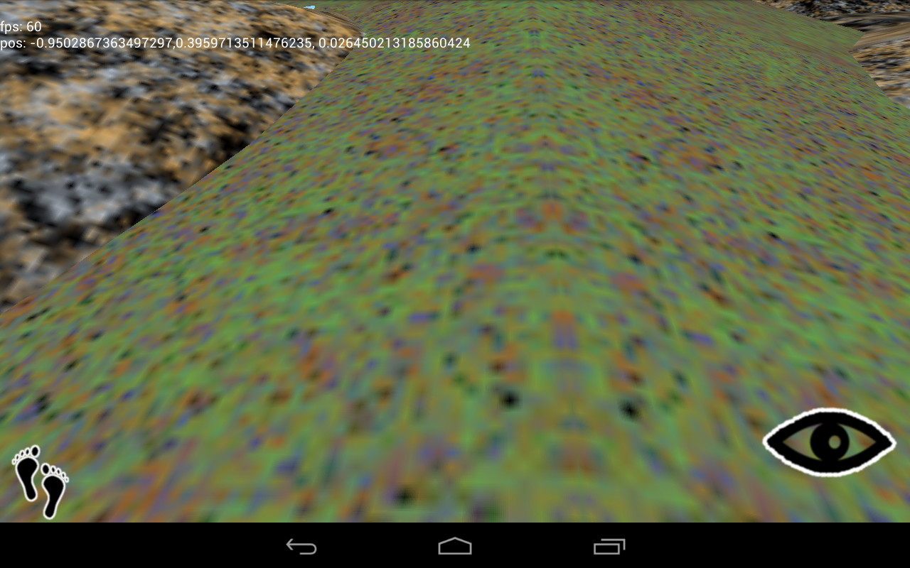
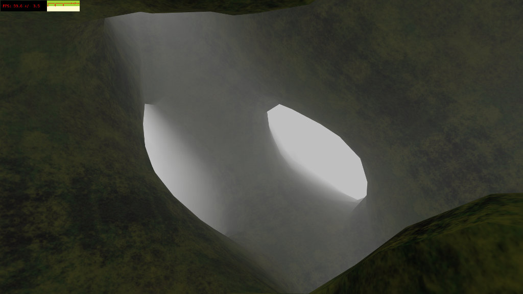
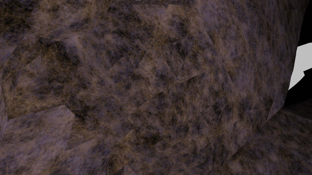
You’ll find these artifacts all over the scene. They’re caused by reflection, as the texture coordinates run from 0 to 5 and back again. I haven’t had much luck getting rid of them so far. The best strategy I’ve found is choosing my textures such that the artifact isn’t as prominent.
Let’s go back to the fragment shader. As mentioned before, we can’t find an exact set of texture coordinates for a given point on an arbitrary surface, so we blend together the three texture planes to get a final result.
/** fragment shader **/

precision mediump float;

uniform sampler2D texture;

varying vec3 con;
varying vec3 tex;

void main(void) {
	gl_FragColor = con.z * texture2D(texture, tex.xy) + con.x * texture2D(texture, tex.yz) + con.y * texture2D(texture, tex.xz);
}
Texture memory lookups are fast, even on mobile GPUs, but it’s still a lot of code just to generate a pixel. (Some GPUs will optimize an expression like this into a couple of multiply-add-accumulate instructions. I wouldn’t depend on it, though.) Also, I find that blending can distort the internal structure of most textures. The final result might appear washed out and blurry. Sure would be nice if we could perform one single lookup.
Well, we do have the notion of texture planes: xy, yz, and xz. Odds are that every polygon you generate has a plane that it is “mostly” aligned with. Why not go all the way and lock the texture coordinates to that alignment?
public void handlePolygon(Vector v0, Vector v1, Vector v2, Vector normal) {

	double nx = Math.abs(normal.x);
	double ny = Math.abs(normal.y);
	double nz = Math.abs(normal.z);

	/**
		vbuffer format is
			3 floats for position
			2 floats for texture
	**/

	if (nz >= nx && nz >= ny) {
		vbuffer.set(v0.x, v0.y, v0.z, v0.x, v0.y);
		vbuffer.set(v1.x, v1.y, v1.z, v1.x, v1.y);
		vbuffer.set(v2.x, v2.y, v2.z, v2.x, v2.y);
	} else if (ny >= nx && ny >= nz) {
		vbuffer.set(v0.x, v0.y, v0.z, v0.x, v0.z);
		vbuffer.set(v1.x, v1.y, v1.z, v1.x, v1.z);
		vbuffer.set(v2.x, v2.y, v2.z, v2.x, v2.z);
	} else if (nx >= ny && nx >= nz) {
		vbuffer.set(v0.x, v0.y, v0.z, v0.y, v0.z);
		vbuffer.set(v1.x, v1.y, v1.z, v1.y, v1.z);
		vbuffer.set(v2.x, v2.y, v2.z, v2.y, v2.z);
	}
}
Knowing the normal vector, we can determine the closest texture plane, and use the respective vertex positions as texture coordinates. (We could transform the position to relative coordinates as discussed above, instead of doing it in the vertex shader, but I have eliminated this for clarity). Note that each vertex in a single polygon must conform to the same plane, or the texture will be distorted. Now, we can simplify everything.
/** vertex shader **/

attribute vec3 position;
attribute vec2 texturec;

uniform mat4 projector;
uniform mat4 modelview;

varying vec2 tex;

void main(void) {
	vec4 pos = modelview * vec4(position, 1.0);
	gl_Position = projector * pos;
	tex = abs(mod(texturec, 10.0) - 5.0);
}

/** fragment shader **/

precision mediump float;

uniform sampler2D texture;

varying vec2 tex;

void main(void) {
	gl_FragColor = texture2D(texture, tex);
}
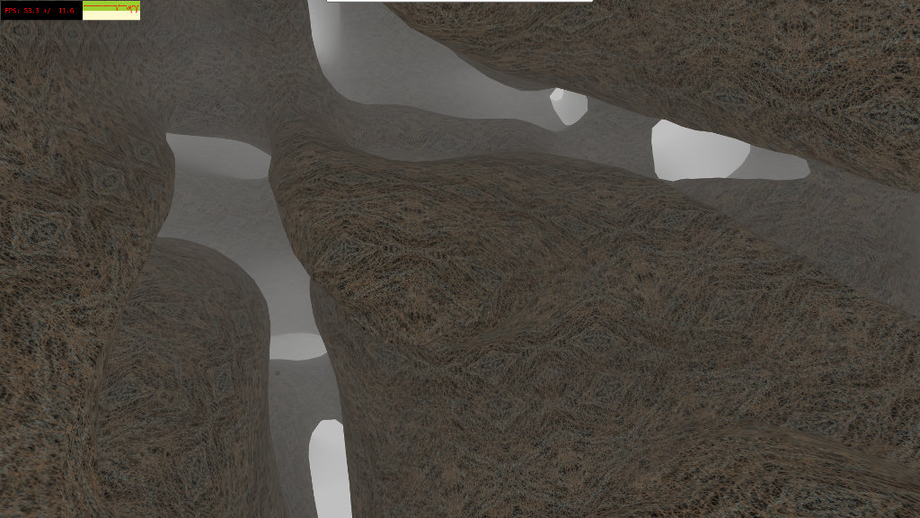
The technique works best for large areas with little curvature.
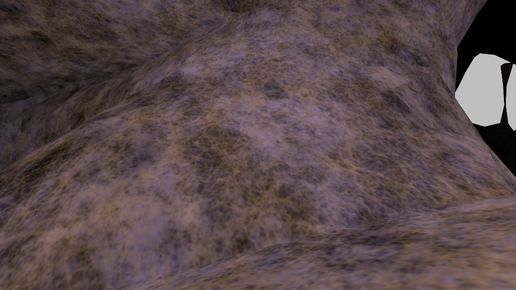
There are visible boundaries where the texture plane changes. Of course, where there is a great deal of curvature, the boundaries are more noticable.
Minimizing these artifacts requires choosing your surfaces such that sharp angles are hidden from the player. Also, textures with little internal structure won’t look as bad if you can’t hide the boundaries. As with most aspects of computer graphics, you get the best results by cheating.