freebeard: algorithmic music for android

My second Android app has hit the Play Store. It’s called Freebeard, and it makes music.

freebeard-1

That’s it, pretty much. The whole UI is just a notification. The application runs inside a service. Here’s a sample of the output:

It grew out of a simple experiement. I yanked the synthesizer module out of Quencher, and yoked it to a Markov chain initialized with random data. The result was interesting, though nothing I’d listen to for long. If the chain contained a few nodes, it would repeat the same note patterns endlessly. Adding more nodes created more variations, but also increased the randomness of the output. A melody that wanders everywhere and goes nowhere is just as boring as an endlessly repeated note. What I needed was some way of bringing long-term patterns into the music to be modulated and mutated over time.

Chains with few nodes create recognizable patterns. What if I built an array of them, and switched from one to the next as the music progressed? That works, but it’s still kind of boring, because once you play through the entire array, you have nowhere to go but back to the beginning. Moving through the chains in random order mixes things up, but it’s the wrong kind of mixing up. It’s patternless and unrepeatable.

Obvious solution? Drive the array with another little Markov chain. A chain of chains, if you like. That way, you have second-order effects, a larger pattern driving the smaller ones. I create all the improvisational lines, rhythm patterns, and chord changes this way. It’s simple, but there’s a whole lot of stuff that comes out of that simplicity.

let’s make lots of echoes: building a simple reverb

Having drifted into video for a bit, I’m back into audio, and putting together an exciting thing that I’ll be releasing soon. For this new project, I needed to sweeten the output of an audio synthesizer: add a little warmth, a little depth, that sort of thing. Give it atmosphere. How about some reverb? Sounds good!

So, what exactly is reverb? It’s the sum total of many, many echoes combining with the original signal. Imagine a musician playing in a large chamber. Sound waves from her instrument will bounce from the near wall, the far wall, the ceiling above her head, the floor twenty feet away, and so on, and each echo will bounce into other bits of the chamber, and so on, and so on. The echo intervals are very small–like fractions of a millisecond small. The totality of all these echoes, and echoes of echoes, produces a sort of low mutter that decays slowly. When applied to an audio signal it adds a sense of space, of location.

There are many algorithms that can provide reverb. Some involve convolution, others combine filters. I didn’t need anything too complex or configurable, and it’s been said that one can build nearly any effect out of delay lines. I decided to give it a try. Here’s what I came up with.

/**
 * implement circular delay buffer with multiple feedback paths
 */
public class Delay {

	static int Length = 8192;
	static int Modulus = Length - 1;

	static float Mixer = 0.95f;

	float[] buffer = new float[Length];
	int reader;
	int writer = Length >> 1;
	int[] path = new int[8];

	public Delay() {
		relocate();
	}

	/**
	 * recreate feedback paths to relocate echoes
	 */
	public void relocate() {
		Random rng = new Random();
		for (int i = 0; i < path.length; i++) {
			path[i] = rng.nextInt();
		}
	}

	/**
	 * process the next sample
	 */
	public float process(float s) {
		for (int i = 0; i < path.length; i++) {
			int w = (writer + path[i]) & Modulus;
			buffer[w] = s * (1f - Mixer) + buffer[w] * Mixer;
		}
		writer++;
		return buffer[(reader++) & Modulus] + s;
	}

}

Let’s see. The buffer size isn’t configurable but could be made so. Just make sure it’s a power of two, as I’m using one of my favorite buffer tricks: bitwise-AND modulus, which prevents indices from running over the length without hitting a conditional or an expensive divide-based modulus.

The path array represents a small number of feedback paths randomly distributed across the buffer that provide echo sources. Calling relocate() will shuffle them around. The user calls process() and supplies an audio sample, receiving in return the sample mixed with reverb. Inside the call, the sample is placed wherever the paths dictate, blending it with whatever’s already there.

The effect it produces is not nearly as impressive as you can get with more complex algorithms or DSP hardware, but for my application, it’s perfect. It gives the flat output of the synthesizer a subtle depth–a sense of having been recorded live rather than generated, and that’s all I needed.

ADDENDUM:

For best performance, you’ll want to submit a sample buffer to the delay object instead of trying to process one sample at a time. Here’s an implementation of the process() method that does this.

public void process(float[] sample) {
	for (int i = 0; i 


roll that camera, zombie: rotation and conversion from YV12 to YUV 420 Planar

In our last episode, I was converting the NV21 image format from my Android device’s camera into the more display-friendly RGB. However, now that I’m trying to push the images over a network, I’m having to run them through a video codec, and the list of color formats supported by the codec is…hilariously small. Literally, there are two available formats and neither one will work directly with the camera. The closet match is between the YV12 image format (supported by all Android cameras) and the YUV 420 Planar image format (supported by all Android codecs).

The catch? The two formats have their U and V chroma planes swapped, making everyone look as if they just stepped out of a zombie flick.

Image rotation is another problem. When I rotate the device, the camera rotates and the display rotates, but the image data has no idea about any of this. Turn the device upside-down, and the feed from the camera shows an upside-down room. This is not what I want.

I’m in a generous mood. Let’s solve both issues.

I can get the current orientation state of the device from the window manager, then use the base orientation of the camera to derive a rotation for the image. I’ve adapted some code from the Android docs to do just that. (I can’t use Camera.setDisplayOrientation() to solve the rotation problem because it doesn’t affect the camera output, just the preview display.)

private int getRotation() {
	Display display = getWindowManager().getDefaultDisplay();
	int rotation = display.getRotation();
	int degrees = 0;
	switch (rotation) {
	case Surface.ROTATION_0: degrees = 0; break;
	case Surface.ROTATION_90: degrees = 90; break;
	case Surface.ROTATION_180: degrees = 180; break;
	case Surface.ROTATION_270: degrees = 270; break;
	}
	int result = 0;
	if (cameraInfo.facing == CameraInfo.CAMERA_FACING_FRONT) {
		result = (cameraInfo.orientation + degrees) % 360;
		result = (360 - result) % 360;	// compensate the mirror
	} else {
		result = (cameraInfo.orientation - degrees + 360) % 360;
	}
	return result;
}

Once I’ve got the rotation state I apply to it the image. We assume that the input and output buffers are the same size.

public static void rotateY12toYUV420(byte[] input, byte[] output, int width, int height, int rotation) {
	boolean swap = (rotation == 90 || rotation == 270);
	boolean flip = (rotation == 90 || rotation == 180);
	for (int x = 0; x < width; x++) {
		for (int y = 0; y < height; y++) {

I’m breaking the rotation into two components: swap and flip. Swap means swapping the x & y coordinates, which provides a 90-degree rotation, and flip means mirroring the image for a 180-degree rotation. We do the following for each pixel in the image.

			int xo = x, yo = y;
			int w = width, h = height;
			int xi = xo, yi = yo;
			if (swap) {
				xi = w * yo / h;
				yi = h * xo / w;
			}
			if (flip) {
				xi = w - xi - 1;
				yi = h - yi - 1;
			}
			output[w * yo + xo] = input[w * yi + xi];

I make copies of the x/y and width/height because I’m going to manipulate those values. If we’re swapping x and y, I have to stretch them as I can’t guarantee that the width and height of the image are the same. Flipping the image simply reverses it in both x and y. Note that I’m iterating over the output coordinates to derive the input coordinates. I tried it the other way originally and found that it left gaps in the final image where two sets of input coordinates mapped to the same output coordinates. Doing it this way ensures that all output pixels are covered. This takes care of transforming the Y (or intensity) plane of the YUV format, but there’s two more planes to deal with.

			int fs = w * h;
			int qs = (fs >> 2);
			xi = (xi >> 1);
			yi = (yi >> 1);
			xo = (xo >> 1);
			yo = (yo >> 1);
			w = (w >> 1);
			int ui = fs + w * yi + xi;
			int uo = fs + w * yo + xo;
			int vi = qs + ui;
			int vo = qs + uo;
			output[uo] = input[vi]; 
			output[vo] = input[ui]; 
		}
	}
}

In the second half, I transform and swap the UV planes. Both YV12 and YUV420  feature sub-sampled color planes. Each plane is half the width/height of the Y plane, and therefore a quarter of the size (if size = width * height, then width/2 * height/2 = size / 4). To locate a pixel in these planes, we divide all our x and y coordinates by two. We’re using width as our stride, so that also gets divided by two. Planar offsets into the image can be found by using the size of the Y plane (width * height) and the size of a chroma plane (width * height / 4). Don’t forget to swap the UV planes between input and output!

Update: I’ve had requests for a version of this routine that works for NV21 format. Here it is:

public static void rotateNV21toYUV420(byte[] input, byte[] output, int width, int height, int rotation) {
	boolean swap = (rotation == 90 || rotation == 270);
	boolean flip = (rotation == 90 || rotation == 180);
	for (int x = 0; x > 2);
			xi = (xi >> 1);
			yi = (yi >> 1);
			xo = (xo >> 1);
			yo = (yo >> 1);
			w = (w >> 1);
			h = (h >> 1);
			// adjust for interleave here
			int ui = fs + (w * yi + xi) * 2;
			int uo = fs + w * yo + xo;
			// and here
			int vi = ui + 1;
			int vo = qs + uo;
			output[uo] = input[vi]; 
			output[vo] = input[ui]; 
		}
	}
}	

making YUV conversion a little faster

As part of my next Android project, I’ve been working with the hardware camera. All implementations of the Android stack are required to support the NV21 format, so I’m going with that. For some reason that I’m sure makes perfect sense, there isn’t an Android API for converting between YUV and RGB formats, so you have to roll your own. This routine I dug out of Stack Overflow works fine.

public static void YUV_NV21_TO_RGB(int[] argb, byte[] yuv, int width, int height) {
    final int frameSize = width * height;

    final int ii = 0;
    final int ij = 0;
    final int di = +1;
    final int dj = +1;

    int a = 0;
    for (int i = 0, ci = ii; i > 1) * width + (cj & ~1) + 0]));
            int u = (0xff & ((int) yuv[frameSize + (ci >> 1) * width + (cj & ~1) + 1]));
            y = y  255 ? 255 : r);
            g = g  255 ? 255 : g);
            b = b  255 ? 255 : b);

            argb[a++] = 0xff000000 | (r 

My only issue is that I'm using it in a preview callback--converting and using the image data in real time--and it's not fully optimized for that. The frame rate drops from 15fps to 8-10fps.
The major culprit appears to be the floating point conversions between the YUV and RGB planes.

int r = (int) (1.164f * (y - 16) + 1.596f * (v - 128));
int g = (int) (1.164f * (y - 16) - 0.813f * (v - 128) - 0.391f * (u - 128));
int b = (int) (1.164f * (y - 16) + 2.018f * (u - 128));

Fortunately, there's a simple fix. Scaled integers to the rescue!

int a0 = 1192 * (y - 16);
int a1 = 1634 * (v - 128);
int a2 = 832 * (v - 128);
int a3 = 400 * (u - 128);
int a4 = 2066 * (u - 128);
	            
int r = (a0 + a1) >> 10;
int g = (a0 - a2 - a3) >> 10;
int b = (a0 + a4) >> 10;

I've multiplied each floating point constant by 1024 and truncated it. Now I can add/subtract the scaled integers, and apply a bit shift right to "divide" each result by 1024. With this change, the frame rate is back up to 15fps.

a slightly irritated rant

My music-creation app Quencher is currently available on Google Play. However, I’d heard that Amazon’s App Store would be a good place for a tablet app, so I went ahead and made a developer account, gave them my tax information and bank details and so on. As I was trying to create the actual application listing, I came across this little gem.

wtf-amazon-1

Yeah, it’s a required field. Now, I understand that phone support is a nicety, and I’m not opposed to talking with customers. The problem is that I’d rather not give out my personal phone number, and a second phone line really isn’t possible right now. Well, no big deal; I’m sure we can resolve this peaceably. I’ll just give their developer support line a call.

wtf-amazon-2

Ah-ha. Thanks, Amazon!

mapping the broken city

I was back experimenting with procedural textures when I managed to produce this gem.

brokencity

I took one look at it and thought, that’s a city. There’s roads and blocks and buildings, though it does look as if no one’s been there for a long time. An old city, then, crumbling into ruins. A broken city.

I didn’t have much use for it as a texture, but I liked it enough to want to see more of it, so I decided to make a map of that old, broken city.

Grab the source. Here’s the breakdown.

There are three files: index.html, map.js, and worker.js. The HTML document doesn’t do much beyond hosting the Javascript, so forget about it. The map.js module contains all the UI code, and worker.js is a web worker that handles the actual image generation.

When map.js is loaded, it first runs onInit() to create the canvas, set up the event handlers, and start the web worker. A call to onResize() insures the canvas fills the document area, and kicks off the onDraw() routine, which draws the map image to the canvas. It doesn’t do it all in one go, however.

The map is very large, so it has to be created and displayed in chunks. Each chunk is 256 by 256 pixels. The onDraw() routine checks the viewport (which tracks the current scroll position) to determine which chunks should be visible to the user, and queries a hash table as to which chunks actually exist. Those that do are copied to the canvas at the correct position. Those that don’t are displayed as empty regions, and a request message is posted to the web worker.

The image generation code in the web worker is based on Perlin noise–summing over frequencies of a random function. To create an image, we need a two-dimensional source. To keep things simple, I’ll use a function of the form f(x, y) = a(b(x) + c(y)) where a, b, and c are functions that return a number in the range [0..1] for any real number. This lets me keep the source data in one-dimensional buffers, which are a little easier to manipulate.

Each buffer is populated with random-sized “blocks”, and each block simply repeats a random decimal. These define the regions of the city: dark spots and light spots. Interpolation between each block makes thin transitional areas: roads and bridges. Perlin noise is usually additive, but I found that multiplication provides greater contrast.

Once an image chunk is complete, the web worker posts it back over to the main ui, which handles it in the onChunk() routine. Each chunk is copied to an ImageData object, which is added to the hash table. A call to onDraw() gets the new chunk onto the screen. We also go through the list of available chunks to remove any that are very far away from the current viewport. That way, the memory footprint doesn’t grow too large.

So, that’s how I map the broken city. Happy exploring! If you can make use of the code, feel free to do so.

constructing an arbitrary scale

One of my goals in creating Quencher was to let users venture into experimental areas of composition. Microtonal scales have a long history both within Western music and outside of it, and the app permits would-be composers to construct such scales and use them in scores.

Here’s a functional (though simplified) Javascript version of the scale editor.

Tone Interval Pitch Number / Sum Frequency (Hz)


The tone frequencies are derived from the equal-temperament system of tuning, where the frequency of each note is a constant multiple of the one before it. For the twelve-tone Western scale, that constant is the twelfth root of two, or approximately 1.059463.

Why this number? Each octave doubles the frequency: the A above middle C is 440 Hz, and the next A above that is 880 Hz. For twelve tones, we’re dividing that doubling effect into twelve equal parts. If I multiply A (440Hz) by the twelfth root of two, I get 466.16 Hz, which is the frequency for the next note (B♭). Sweet!

There’s nothing sacred about twelve tones, of course. Want a fifteen-tone scale? Just take the fifteenth root of two, pick a starting frequency–say, middle C (261.63 Hz)–and keep multiplying to get each successive frequency. Or, you can use this handy formula.

Frequency = ReferenceFrequency * pow(NthRootOfTwo, PitchNumber);

Now, each tone has a “pitch number”, a simple integer that we can increase or decrease by 1 to go up or down the scale. Find the Nth root of two, where N is the number of tones in the scale, and raise it to the power of the pitch number to get the multiplier for that specific pitch. The reference frequency defines what the frequency is for a pitch number of zero.

This works fine when all the tones are the same distance from one another. However, this isn’t always the case. A major scale has the following interval formula: 2 – 2 – 1 – 2 – 2 – 2 – 1. It has seven tones, but obviously, not all are weighted the same. How do we generate it? Let’s revise the formula above.

Multiplier = pow(2, 1 / IntervalSum);
Frequency = ReferenceFrequency * pow(Multiplier, PitchNumber);

Instead of using the number of tones as the basis for the constant multiplier, we’re using the sum of the interval values. For the major scale, that’s 2 + 2 + 1 + 2 + 2 + 2 + 1 = 12, which looks familiar enough. The pitch numbers we plug into the formula are calculated by taking a running sum of intervals: 0, 2, 4, 5, 7, 9, 11, and 12. (For a twelve-tone scale originating at middle C, that’s C, D, E, F, G, A, B, and C). This way, you can easily define scales that are subsets of larger scales.

(Shameless plug: if I’ve piqued your interest, why not try the real thing? Quencher is a free download for Android.)

Also, feel free to download the source code for this example and do whatever you like with it. It uses the RIFFWAVE library, which is a lifesaver for anyone trying to do cross-browser HTML audio.

it’s a banner year

Humans have a psychological need to decorate their spaces, and our blogs are no exception. Even those of us who prefer a minimalist approach, and loudly demand that the content be the focus aren’t immune to this; I can’t tell you how many tech blogs I’ve read that are just black text on a white page but use code to make the sidebar vibrate. Way to let me focus, dude. wiggle wiggle wiggle wiggle arrgh

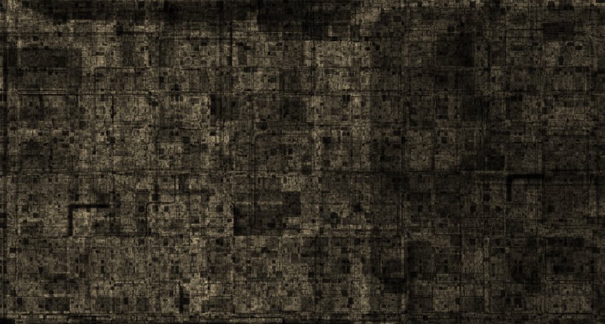
I like a little decoration, and a little dynamism too, so one recent change to the blog is the header image above. It’s a dynamically generated canvas that changes on every page refresh. Grab the code. Here’s a breakdown of how it works.

The whole thing runs inside a self-executing closure to keep its variables private. We generate a random color and its complement, plus a couple of large pseudo-random numbers that we’ll be using for pattern generation.

(function() {

	// select color and complement
	var color0 = {r: 256 * Math.random(), g: 256 * Math.random(), b: 256 * Math.random() };
	var color1 = {r: 256 - color0.r, g: 256 - color0.g, b: 256 - color0.b };

	// select pseudorandom coefficients
	var a0 = 2234958 * Math.random() + 38402;
	var a1 = 7459483 * Math.random() + 80984;

The banner is tailored for WordPress, which gives its header element the masthead id. We want our canvas to have the same height as the masthead. This value shouldn’t change while the page is loaded. However, we can’t guarantee that the width of the masthead won’t change (by resizing or change of orientation on a mobile device), so we pick a maximum width that should cover most scenarios.

	// locate wordpress header element
	var header = document.getElementById("masthead");
	var width = 2048;
	var height = header.clientHeight;

We want to shim the canvas into place “under” the header, without disrupting any other elements. I insert it into the DOM just before the page element that contains the header. Absolute positioning allows the canvas to be placed without changing the flow.

	// create canvas and draw buffer
	var canvas = document.createElement("canvas");
	canvas.style.position = "absolute";
	canvas.width = document.body.clientWidth;
	canvas.height = height;
	document.body.insertBefore(canvas, document.getElementById("page"));

We’re going to draw a pattern directly onto an image buffer, so here it is. The set() function draws a single RGB pixel to an XY position in the buffer (at full opacity).

	var context = canvas.getContext("2d");
	var image = context.createImageData(width, height);

	// set a pixel in draw buffer
	function set(x, y, r, g, b) {
		var i = (Math.floor(x) + Math.floor(y) * image.width) * 4;
		image.data[i++] = r;
		image.data[i++] = g;
		image.data[i++] = b;
		image.data[i  ] = 255;
	}

Things start to get interesting. The header image is a sort of contour plot drawn in two colors, with black lines separating distinct areas. We interpolate RGB values based on the value of k, and the two colors we generated above. The black borders occur when m is near zero. Left alone, the output of this is rather flat and unaesthetic, so I add a little noise to give it a grainy effect.

	// set interpolated pixel in draw buffer
	function interp(x, y, k, m) {
		var r = (1 - k) * color0.r + k * color1.r;
		var g = (1 - k) * color0.g + k * color1.g;
		var b = (1 - k) * color0.b + k * color1.b;
		// borders
		r = r * m;
		g = g * m;
		b = b * m;
		// noisify
		r = r + (Math.random() * 20 - 10);
		g = g + (Math.random() * 20 - 10);
		b = b + (Math.random() * 20 - 10);
		set(x, y, r, g, b);
	}

As Javascript does not include a seedable 2D noise generator, I’ve rolled my own using nested trig functions with very high frequencies. Small changes in X and Y produce large changes in the output, and the trig functions provide a useful output range. The seeds (a0, a1) were generated above in the first step.

To produce the actual contours, we interpolate across the noise source in two dimensions. This is the same technique used in Perlin noise (and many examples and projects from this blog).

	// map a pseudorandom number to a point
	function randm(x, y) {
		return Math.sin(a0 * Math.sin(x * a1 + a0) + a1 * Math.cos(y * a0 + a1));
	}

	// interpolate a color value for a point
	function source(x, y) {
		var mx = x;
		var my = y;
		var ix = Math.floor(mx);
		var iy = Math.floor(my);
		mx = mx - ix;
		my = my - iy;
		var dx0 = (1 - mx) * randm(ix, iy) + mx * randm(ix + 1, iy);
		var dx1 = (1 - mx) * randm(ix, iy + 1) + mx * randm(ix + 1, iy + 1);
		return (1 - my) * dx0 + my * dx1;
	}

To actually generate the contour plot, we get the value of the source function at each (normalized) point in the image buffer. Eight distinct regions are created by rounding the value to its nearest one-eighth. The boundary between each region is where the fractional part of the source (times eight) is near zero, and we run that value through a power function to shape it into a thin pencil line.

	// for each point in the buffer	
	for (var x = 0; x < width; x++) {
		for (var z = 0; z < height; z++) {
			var xx = 2 * (x / width - 0.5);
			var zz = 2 * (z / height - 0.5);
			var k = (source(xx, zz) + 1) * 0.5;
			var l = Math.floor(k * 8) / 8;
			var m = k * 8;
			m = m - Math.floor(m);
			m = Math.pow(Math.sin(Math.PI * m), 0.1);
			interp(x, z, l, m);
		}
	}

The completed image is drawn to the canvas. If the browser window is resized, we need to match the canvas width to the header width, and redraw the image to insure it’s fully visible.

	context.putImageData(image, 0, 0);
	window.onresize = function(event) {
		canvas.width = document.body.clientWidth;
		context.putImageData(image, 0, 0);
	};
})();

It would be possible, of course, to animate the image. The source function is defined for all real numbers, so I could scroll it infinitely in one direction or another. Eye-catching? Certainly. Missing the point? Maybe. To paraphrase a T-shirt: hey, my content is down here.

quencher: make some music

Government shutdown got you down? Need a little music in your life? Artisinal, hand-crafted, locally-sourced music? 

Allow me to introduce Quencher for Android.

feature

Quencher allows you to hear music the old-fashioned way: by laboriously entering it in by hand. None of this decadent, new-fangled “pre-recorded” nonsense– you’ll write your own music, the way God intended, note by note.

You can work from all the usual major, minor, and pentatonic scales, but if you’re feeling adventurous, create your own! Six tones? Nine tones? Fractional intervals? A note called “P” right in the middle? Go nuts!

Don’t like the instruments I’ve included? Well, you know where you can go…that’s right, to the instrument editor! Create your own instruments out of hand-sculpted waveforms and use them in your songs. Sprinkle a little vibrato on top, or maybe a little tremolo if you’re in that kind of mood.

And as I’m a generous sort, you can “save” your creations to disk, then “load” them back to enjoy at any time. No need to thank me, citizen. Just doing my job.

Quencher is now available on the Google Play for FREE and a smile. (Smile not required.)

dusting off the blog

So, I’ve been busy the last several months, putting together my first commercial Android app, checking in every few weeks to collect the spam and make sure no one’s broken in and so on. Learning a new operating system is always an intense experience, and moving from a desktop mentality to a mobile frame of mind has made it doubly so. But the app is complete, and while I can’t promise I’m going to jump right back into JavaScript and WebGL and odd games about literate gasbags, I do intend to increase the frequency of the posting. It’s been entirely too quiet around here.