overdrawn at the indexing bank

In the last post, I talked about two issues that affect surface texturing on mobile devices. Mobile GPUs tend to have a smaller floating point precision than their desktop cousins, which limits the range of our texture coordinates, and less power, which limits the complexity of our fragment shaders. Next, I’d like to address two issues that are less specific to mobile GPUs, but make a big difference in the final framerate.

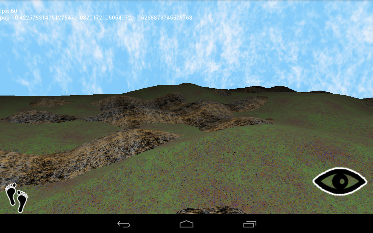
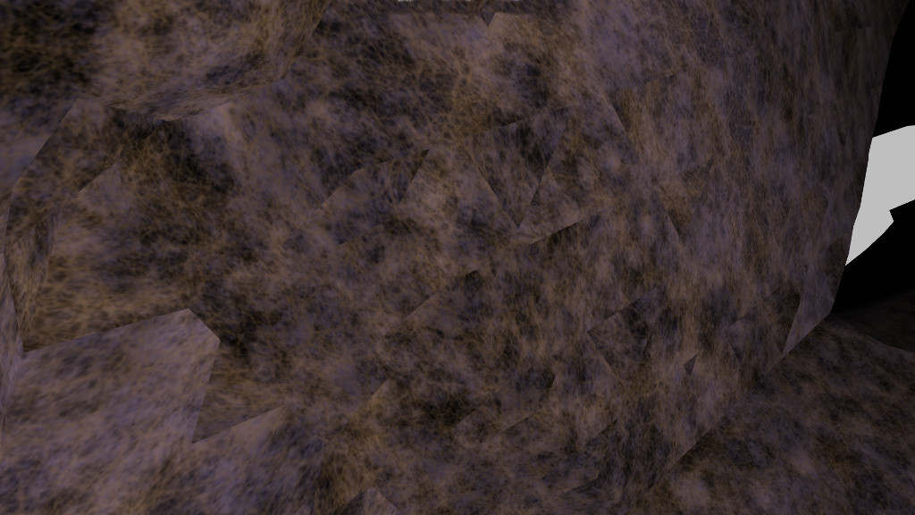
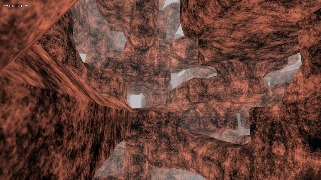
When drawing multiple intersecting surfaces—a landscape with rocks and hills, for example—it’s tempting to ignore overdraw, a condition where areas of the screen can be painted over multiple times. Modern GPUs are fantastic at eliminating hidden surfaces within a single drawcall, and hardware depth-testing avoids this problem across multiple drawcalls. So it seems silly to worry about. Just draw everything, right?

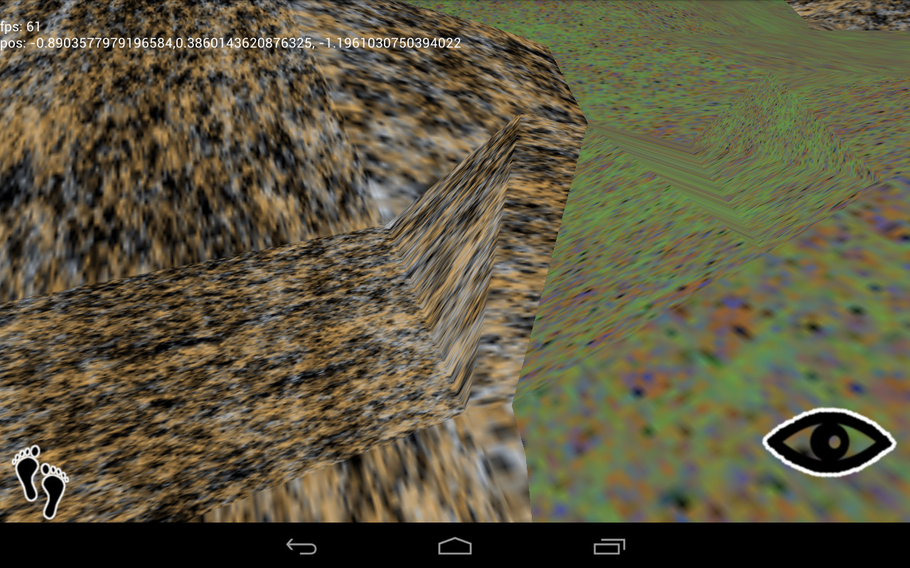
However, complex scenes can still cause trouble. I find that drawing one object in front of another doesn’t cause a performance hit, but when two surfaces intersect such that each is partially inside the other, the resulting complexity bogs the GPU down.

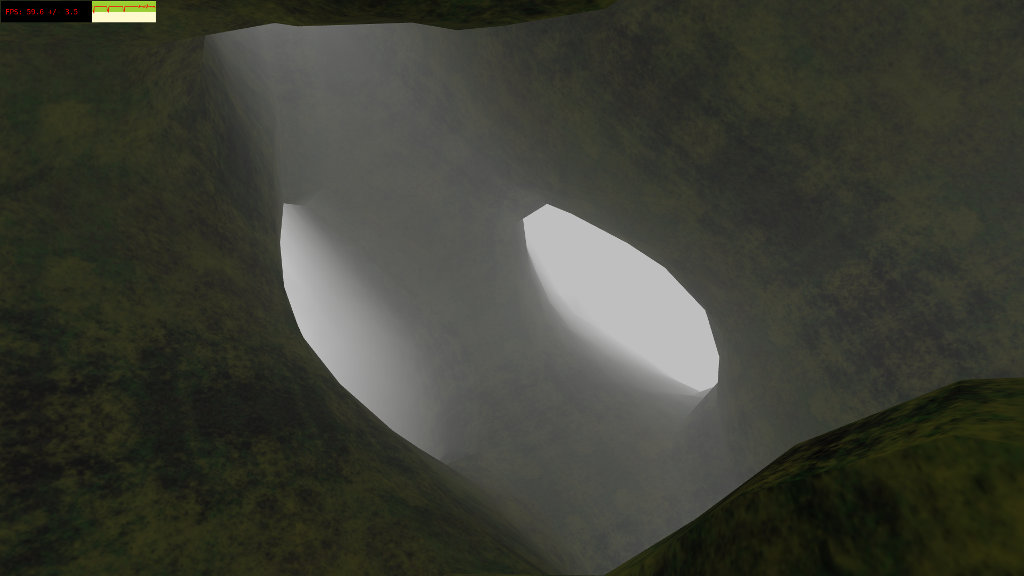
In my current game project, I’m using scalar fields to represent (and generate) all surfaces (see my previous posts on this subject), which makes collision detection easy. To see if a point lies within a surface, I check the field value at the point. To see if a polygon falls within the surface, I check each vertex in turn.

/**
 * determines if a polygon is entirely inside the isosurface
 * @param v0, v1, v2 vertexes of the polygon
 * @return true if polygon is inside
 */
public boolean inside(Vector v0, Vector v1, Vector v2) {
	return getField(v0.x, v0.y, v0.z) 

Happily, this provides a simple solution to the overdraw problem. I can easily test whether a polygon is contained by any surface other than its owner.

/**
 * determines if a polygon will intersect multiple surfaces
 * 
 * @param self calling object
 * @param v0, v1, v2 vertexes of the polygon
 * @return true if polygon intersects multiple surfaces
 */
public boolean mayOverdraw(Base self, Vector v0, Vector v1, Vector v2) {
	if (self != ground && ground.inside(v0, v1, v2))
		return true;
	if (self != stone && stone.inside(v0, v1, v2))
		return true;
	if (self != rocks && rocks.inside(v0, v1, v2))
		return true;
	
	return false;
}

When building the surface, I reject any polygon that fails the test.

/**
 * 
 * polygonization superclass
 * 
 */
class ASurfacer extends Surfacer {

	public double field(double x, double y, double z) {
		return getField(x, y, z);
	}
	
	public void build(Vector v0, Vector v1, Vector v2, Vector n) {

		// reject polygons inside other surfaces
		if (!world.mayOverdraw(caller, v0, v1, v2))
			handlePolygon(v0, v1, v2, n);
	}
}

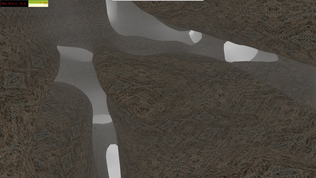
In my current game project, using this technique bumped the frame rate from 40 to 50. It also prevented sudden dips in frame rate caused by multiple intersecting surfaces in the scene.

If you're generating heightmaps, indexing your polygons is a no-brainer. It's easy to map integers to the points of a 2D grid. When I started working with arbitrary surfaces and marching cubes, this was the method I came up with.

// callback for building surface mesh
function polycb(p) {
	gradient(n, p.x, p.y, p.z);
	var key = Math.floor(p.x * 100) + "." + Math.floor(p.y * 100) + "." + Math.floor(p.z * 100);
	var ent = hash[key];
	if (ent !== undefined) {
		mesh.index(ent);
	} else {
		mesh.set(p.x, p.y, p.z, n.x, n.y, n.z);
		mesh.index(indx);
		hash[key] = indx++;
	}
}

It works, but relies on a truly cringeworthy key generation formula (note to past self: just because you can discard precision doesn't mean you should), as well as having a fast hashing algorithm under the covers. When I ported this to Android, the results were less than stellar, and I had to find a better approach.

/**
 * Index generator for 3D vertexes
 * 
 * implements an octree in a fixed-size array;
 * as the mesh object only allows short ints
 * to be used for indexes, we don't bother to
 * make the array length > 64k
 * 
 * @author chris
 *
 */

public class Vindexer {

	static public final int INDEX_MASK = 0xFFFF;
	static public final int ADD_VERTEX= 0xFFFF0000;
	
	static private final int MAX_INDEX = 65536;
	static private final float MIN_LIMIT = 0.0001f;

	private float[] vertex;
	private int[] child;

	private int length;
	
	private int hits;
	
	/**
	 * constructor, generates fixed array
	 */
	public Vindexer() {
		vertex = new float[3 * MAX_INDEX];
		child = new int[8 * MAX_INDEX];
		reset();
	}
	
	/**
	 * call prior to generating new indexes
	 */
	public void reset() {
		length = 0;
		hits = 0;
	}
	
	/**
	 * check that a specific vertex is in the octree,
	 * create it if it isn't. either way, return the
	 * index of the vertex.
	 * 
	 * if the indexer hasn't seen this vertex yet, I
	 * assume the calling code needs to add it to a
	 * vertex buffer, so the ADD_VERTEX flag is ORed
	 * with the index. typically, you'd do something
	 * like this:
	 * 
	 * 		int result = vindexer.check(x, y, z);
	 * 		int index = result & Vindexer.ADD_VERTEX
	 * 		if (index != result) {
	 * 			// add vertex to buffer
	 * 			vertexbuffer.set(x, y, z);
	 * 		}
	 * 		indexbuffer.set(index);
	 * 
	 * 
	 * @param x, y, z coordinates of vertex
	 * @return index of new or stored vertex, maybe ORed with 
	 * ADD_VERTEX if new vertex (see above)
	 */
	public int check(float x, float y, float z) {
		int vin, cin, index = 0;
		
		while (index  vx) ? 4 : 0) + ((y > vy) ? 2 : 0) + ((z > vz) ? 1 : 0);
			if (child[ch] != -1) {
				index = child[ch];
			} else {
				child[ch] = (int)length;
				index = length;
			}
			
		}

		// no entries found, create one
		vin = length * 3;
		cin = length * 8;

		vertex[vin] = x;
		vertex[vin + 1] = y;
		vertex[vin + 2] = z;

		for (int i = 0; i = MAX_INDEX) {
			throw new RuntimeException("Vindexer exceeded index limits");
		}
		
		// return index with "add vertex" flag in upper word
		return index | ADD_VERTEX;
	}
	
}

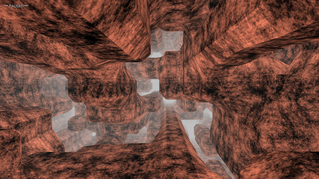
Implementing an octree using fixed arrays might be considered a criminal offense in some jurisdictions, but I thought it made sense here for two reasons. First, generating a mesh large enough to require indexes greater than 65536 isn't recommended practice for desktops, let alone mobile GPUs, so I felt justified in setting an upper limit. Second, I find that in garbage-collected environments, it's best to throw away as little as possible. The conventional node-based octree implementation would have required throwing out thousands of objects on every surface generation pass. (Remember, I'm generating this stuff in real time, not pulling it from a model file.) Less garbage means fewer collections, and less frame stuttering.

Indexing the surfaces increased the frame rate from 50 to 60, and that's as high as it goes. There aren't too many "massive" framerate optimizations out there, once you eliminate the obvious (don't draw 100 million vertexes), but following a few simple rules of thumb will pay big dividends.

texturing troubles

Generating procedural graphics on a mobile device requires compromise, cutting corners, and a little cheating. Resources are scarce. Specs are limited. You’re creating content in an environment intended for consuming it.

Sound familiar? Trying to develop real-time 3D games in a browser prepared me for some of these challenges, but the Android platform tossed me a few new ones. Most so far have to do with the fine art of texturing a surface.

Let’s say I want to generate a landscape: some ground under my (virtual) feet, a few rocks here and there. Using the marching cubes algorithm, I generate a couple of meshes.

meshes

Applying texture coordinates to an arbitrary surface isn’t an easy problem. In fact, my research turns up no exact solution. One practical solution uses the components of the normal vector to blend the contributions of each texture plane.

/** vertex shader **/

attribute vec3 position;
attribute vec3 normal;

uniform mat4 projector;
uniform mat4 modelview;

varying vec3 con;
varying vec3 tex;

void main(void) {
	vec4 pos = modelview * vec4(position, 1.0);
	gl_Position = projector * pos;
	tex = position;
	con = abs(normal);
}

/** fragment shader **/

precision mediump float;

uniform sampler2D texture;

varying vec3 con;
varying vec3 tex;

void main(void) {
	gl_FragColor = con.z * texture2D(texture, tex.xy) + con.x * texture2D(texture, tex.yz) + con.y * texture2D(texture, tex.xz);
}

Note the use of the absolute position as texture coordinates. This works without a problem on your average desktop GPU. On mobile hardware, however, things break.

pixel1000

What’s that about? Well, the OpenGL spec defines the minimum levels of floating point precision that a GPU must support: lowp, mediump, and highp. Vertex shaders are required to support up to highp, and fragment shaders…aren’t. A desktop GPU has few power constraints and can get away with using higher-precision numbers everywhere.

My Google Nexus 7 tablet uses the Tegra 3 SoC. It defines two types of precision in a fragment shader: fp20 and fx10. The first maps to mediump and is the highest level available. The fp20 format has one sign bit, six bits for the exponent, and all of thirteen bits for the mantissa, giving it a precision of 2^-13, around 0.0001. Any smaller number is going to be rounded off.

A 256×256-sized texture requires a precision of 1 / 256, around 0.001, to render all of its detail. This isn’t a problem, right? We’ve got one order of magnitude more than we need.

Well, that’s true as long as we stick to normal UV coordinates between [-1, 1]. But if we use absolute position coordinates, as in the planar blending method above, it’s not long before our coordinates are out of that range. Once the coordinates start going over 10, we’re using more and more of our limited precision to store the integer component at the expense of the fractional component, which is rounded off.

increasing pixelization at z= 10, 100, and 1000

increasing pixelization at z= 10, 100, and 1000

Yuck. Why not use just the fractional component?

/** vertex shader **/

attribute vec3 position;
attribute vec3 normal;

uniform mat4 projector;
uniform mat4 modelview;

varying vec3 con;
varying vec3 tex;

void main(void) {
	vec4 pos = modelview * vec4(position, 1.0);
	gl_Position = projector * pos;
	tex = fract(position);
	con = abs(normal);
}

Yeah, that should work.

fract-distort

Oops. See, the absolute position preserves the continuity of the surface. Across a mesh, there are many polygons that cross texture boundaries. One triangle might have an x-coordinate of 10.2 on one vertex and 11.3 on the next, a distance of 1.1. Take only the fractional component, and you have 0.2 and 0.3, a distance of 0.1, which stretches the texture between those vertexes, distorting the scene.

Is there a better solution? Sort of. The problem arises because the fract() function is discontinuous across integer boundaries. Let’s eliminate that discontinuity.

/** vertex shader **/

attribute vec3 position;
attribute vec3 normal;

uniform mat4 projector;
uniform mat4 modelview;

varying vec3 con;
varying vec3 tex;

void main(void) {
	vec4 pos = modelview * vec4(position, 1.0);
	gl_Position = projector * pos;
	tex = abs(mod(position, 10.0) - 5.0);
	con = abs(normal);
}

Now, we transform the absolute position into a triangle wave that slopes linearly between [0, 5]. Because there is no discontinuity, the relative distance between vertexes is preserved, and as the texture coordinate never rises above 5, we never lose enough floating point precision to drop texture information.

Is there a catch? Well, naturally.

reflect

You’ll find these artifacts all over the scene. They’re caused by reflection, as the texture coordinates run from 0 to 5 and back again. I haven’t had much luck getting rid of them so far. The best strategy I’ve found is choosing my textures such that the artifact isn’t as prominent.

Let’s go back to the fragment shader. As mentioned before, we can’t find an exact set of texture coordinates for a given point on an arbitrary surface, so we blend together the three texture planes to get a final result.

/** fragment shader **/

precision mediump float;

uniform sampler2D texture;

varying vec3 con;
varying vec3 tex;

void main(void) {
	gl_FragColor = con.z * texture2D(texture, tex.xy) + con.x * texture2D(texture, tex.yz) + con.y * texture2D(texture, tex.xz);
}

Texture memory lookups are fast, even on mobile GPUs, but it’s still a lot of code just to generate a pixel. (Some GPUs will optimize an expression like this into a couple of multiply-add-accumulate instructions. I wouldn’t depend on it, though.) Also, I find that blending can distort the internal structure of most textures. The final result might appear washed out and blurry. Sure would be nice if we could perform one single lookup.

Well, we do have the notion of texture planes: xy, yz, and xz. Odds are that every polygon you generate has a plane that it is “mostly” aligned with. Why not go all the way and lock the texture coordinates to that alignment?

public void handlePolygon(Vector v0, Vector v1, Vector v2, Vector normal) {

	double nx = Math.abs(normal.x);
	double ny = Math.abs(normal.y);
	double nz = Math.abs(normal.z);

	/**
		vbuffer format is
			3 floats for position
			2 floats for texture
	**/

	if (nz >= nx && nz >= ny) {
		vbuffer.set(v0.x, v0.y, v0.z, v0.x, v0.y);
		vbuffer.set(v1.x, v1.y, v1.z, v1.x, v1.y);
		vbuffer.set(v2.x, v2.y, v2.z, v2.x, v2.y);
	} else if (ny >= nx && ny >= nz) {
		vbuffer.set(v0.x, v0.y, v0.z, v0.x, v0.z);
		vbuffer.set(v1.x, v1.y, v1.z, v1.x, v1.z);
		vbuffer.set(v2.x, v2.y, v2.z, v2.x, v2.z);
	} else if (nx >= ny && nx >= nz) {
		vbuffer.set(v0.x, v0.y, v0.z, v0.y, v0.z);
		vbuffer.set(v1.x, v1.y, v1.z, v1.y, v1.z);
		vbuffer.set(v2.x, v2.y, v2.z, v2.y, v2.z);
	}
}

Knowing the normal vector, we can determine the closest texture plane, and use the respective vertex positions as texture coordinates. (We could transform the position to relative coordinates as discussed above, instead of doing it in the vertex shader, but I have eliminated this for clarity). Note that each vertex in a single polygon must conform to the same plane, or the texture will be distorted. Now, we can simplify everything.

/** vertex shader **/

attribute vec3 position;
attribute vec2 texturec;

uniform mat4 projector;
uniform mat4 modelview;

varying vec2 tex;

void main(void) {
	vec4 pos = modelview * vec4(position, 1.0);
	gl_Position = projector * pos;
	tex = abs(mod(texturec, 10.0) - 5.0);
}

/** fragment shader **/

precision mediump float;

uniform sampler2D texture;

varying vec2 tex;

void main(void) {
	gl_FragColor = texture2D(texture, tex);
}

The technique works best for large areas with little curvature.

large-area

There are visible boundaries where the texture plane changes. Of course, where there is a great deal of curvature, the boundaries are more noticable.

curvy-area

Minimizing these artifacts requires choosing your surfaces such that sharp angles are hidden from the player. Also, textures with little internal structure won’t look as bad if you can’t hide the boundaries. As with most aspects of computer graphics, you get the best results by cheating.

another four-letter world to explore

As a followup on my last post regarding Rise, here’s a fine little demo that uses it.

mope

(Want to see it in action? Try the Live Demo. WSAD to move, Q for fullscreen.)

Mope uses the marching cubes algorithm to render an arbitrary surface at regular spatial intervals. A web worker performs the rendering, making the transition seamless. The isosurface function also permits simple collision detection.

As in an endless golden thread, the code is arranged around an object containing GL wrapper objects (e.g., texture, mesh, shader) and a worker thread that generates the vertex data, but with Rise, the separation of wrapper and buffer objects makes it easier.

Want to examine the code? There are several key pieces.

Defined in the world object (world.js), this function provides the isosurface. It’s the same one I pointed out a couple posts back. Since both the main thead and the worker thread require it, the function is statically defined in its own little object.

getAnchorField: function(x, y, z) {
	var a = 2 * Math.cos(1.2 * x);
	var b = 2 * Math.cos(0.7 * y);
	var c = 2 * Math.cos(1.3 * z);

	return (Math.sin(x + y + a) + Math.sin(y + z + b) + Math.sin(z + x + c)) / 3;
}

The “anchor” object (anchor.js) maintains the GL wrappers, communicating with the worker thread whenever it needs new vertex data. These two functions provide that communication: send out a request whenever the player has moved a set distance from her last position, and accept the data response when it’s available.

/**
	update the anchor state when necessary
	called for every frame

	@method update
	@param pp player position
**/

update: function(pp) {
	if (M.anchor.lastUpdate.distance(pp) > M.anchor.UPDATE_INTERVAL) {
		M.worker.postMessage( {
			cmd: "update-anchor",
			pos: pp
		} );
		M.anchor.lastUpdate.copy(pp);
	}
},

/**
	handle message event from worker thread
	build the mesh with vertex data

	@method handleWorker
	@param e message object from worker
**/

handleWorker: function(e) {
	if (e.data.cmd === "update-anchor") {
		M.anchor.mesh.build(e.data.vbuffer);
	}
},

Next is the heart of the worker thread (worker.js). It’s called on initialization of the thread to establish both the data buffer and the surface polygon generator.

/**
	initializes anchor objects

	@method initAnchor
**/

function initAnchor() {
	var vbuffer = RISE.createBuffer(Float32Array);

	var step = M.world.ANCHOR_STEP;
	var radius = M.world.ANCHOR_RADIUS;
	var threshold = M.world.ANCHOR_THRESHOLD;

	var source = function(x, y, z) {
		return M.world.getAnchorField(x, y, z);
	};

	var handle = function(v0, v1, v2, n) {
		var nx = n.x * n.x;
		var ny = n.y * n.y;
		var nz = n.z * n.z;		
		vbuffer.set(v0.x, v0.y, v0.z, nx, ny, nz);
		vbuffer.set(v1.x, v1.y, v1.z, nx, ny, nz);
		vbuffer.set(v2.x, v2.y, v2.z, nx, ny, nz);
	};

	var surf = RISE.createSurfacer(radius, step, threshold, source, handle);

	M.generate = function(p) {
		vbuffer.reset();
		surf.generate(p);

		// have to post fake vbuffer object back to main thread
		// as functions (among other types) can't be serialized
		postMessage( { 
			cmd: "update-anchor",
			vbuffer: {
				data: vbuffer.data,
				length: vbuffer.length
			}
		} );
	};
}

The viewer object (viewer.js) handles controls, motion, and collision detection. A smooth surface function makes collision a breeze. Here, I model a spring-like force that increases rapidly as the player approaches the surface, pushing her backward along the normal vector.

// use spring-like force to push camera away from surface
var s = Math.max(0, M.world.getAnchorField(pos.x, pos.y, pos.z)) - 0.05;
var f = Math.pow((1 - s), 128) * 2;
M.world.getAnchorNormal(normal, pos.x, pos.y, pos.z);
normal.mul(f);
direct.add(normal);

And there you have it. Any smooth function can replace getAnchorField above. I would also experiment with the threshold value (which defines where the polygonization is applied). Have fun!

rise of the toolkits

Codebases tend to accumulate cruft. Useful functions accumulate into application classes. Once the classes reach critical mass, they drop below the application layer into libraries. Libraries service multiple projects, consuming all that can be reused.

Now and again, they have to be weeded.

I’ve dropped the Soar toolkit out of active development and folded a copy into the Easy and Gas game projects for their support. I had major changes I wanted to make to the interface, and I couldn’t have maintained those older projects without a compatibility layer that I had no time to write. Instead, I’ve ported everything that was worth saving to a new toolkit project.

Rise improves on its predecessor in several respects. From the README:

* Object model separates constructors and prototypes.
* Buffer/bitmap objects are decoupled from GL wrapper objects.
* Helper functions wrapped in identifying namespaces (math, misc) rather then the main object.
* Non-essential functions from SOAR (heightmaps, noise functions) removed.

Though I love prototypal inheritance, I was never comfortable with how I used it in Soar, so I’ve implemented more of an object factory pattern in Rise. I’ve also removed a couple of embarassing singletons.

Mesh and texture objects now wrap GL objects only. Separate data buffer objects can be more easily allocated, deallocted, and passed across Web Worker boundaries.

I’d gotten into the habit of stuffing every useful function that defied categorization into the main Soar namespace object. Bad idea. I still have a “misc” object, but at least it’s documented as such.

There was so much code in Soar for generating heightmaps, and I’d long moved on to marching cubes and polygonization of arbitrary surfaces. Begone, heightmaps.

I want Rise to become a useful tool for my projects in procedural graphics and generative gaming. If it’s of any use to anyone else, feel free to take it for a spin. I’ll be posting a sample project that uses it very soon.

another universe heard from

Here’s a fun place to visit:

place1

As in the previous post, it’s a no-interpolation scalar field. However, this one is continuous, making normal vectors easier to calculate.

var field = function(x, y, z) {
	var a = 2 * Math.cos(1.2 * x);
	var b = 2 * Math.cos(0.7 * y);
	var c = 2 * Math.cos(1.3 * z);
	
	return (Math.sin(x + y + a) + Math.sin(y + z + b) + Math.sin(z + x + c)) / 3;
};

Changing the constants in the first three lines will create all sorts of wacky alternate realities.

we don’t need no interpolation

Polygonizing a scalar field takes time. The marching cubes algorithm is O(N³), so every unit of radius you want to polygonize increases the processing time by a factor of eight geometrically. The code that implements the scalar field runs within its inner loop. You’ll want this to be as fast as possible.

The set of functions (a) defined for all R³, (b) sufficiently interesting, and (c) fast isn’t a big club. We can create interesting surfaces by interpolating across noise sources (or pseduo-noise sources—see a few posts down), but a 3D interpolation is “fast” only in the sense of running in constant time.

Here’s a pleasant little alternative that I’ve been playing with.

var source = function(x, y, z) {

	var ix = Math.floor(x);
	var iy = Math.floor(y);
	var iz = Math.floor(z);

	return  Math.cos(ix * Math.cos(iy * Math.cos(iz)));
};

The marching cubes algorithm calls this function directly. There is no interpolation step, which cuts total runtime by an order of magnitude. Visually, it’s rough, but a start.

func

There are wide-open spaces and confined areas, plus that all-important sense of structure, making it something more than interpolated noise.

func2

It’s blocky, sure, but there are ways to modulate the field to round the surfaces. I’ll see what else I can come up with in future posts.

an endless golden thread, droid style

Well, you know how it is. You buy a tablet, because tablet. Then what?

I’ve ported my Soar toolkit and my thread demo over to Android. Sources can be found at my GitHub hangout and are free to do whatever you want with.

Android’s not a bad enviroment, and the GUI and OS concepts should be familiar to anyone who’s ever done native application work. Java is…Java. It’s clunky but sort of comfortable after a while, like a bulky jacket on a cold morning, and takes forever to put on. Oh, it looks like something your mother picked out for you. Ha! Buuuuurn.

As WebGL wraps OpenGL ES—also like a jacket of some description—I had little difficulty porting the code. I missed closures and first-order functions, but it wasn’t hard to get back into the Java mindset of packing everything into little class boxes.

In fact, the only area I had to strain my brain was shaders. The GLSL code ports directly, but mobile GPUs aren’t anywhere near as powerful as their desktop pals, so my original shaders lagged horribly. I had to cut them down just to get 30 fps. Then, I found surfaces turning blocky and pixelated over long distances. I texture some surfaces using absolute positions instead of texture coordinates in order to achive long-period patterns. Works fine on the desktop, but on a mobile GPU, the loss of floating point precision has a noticable effect as the numbers get bigger. I have a workaround in place which uses a modulus of the position, but it looks kind of messy in places. Ah well.

again with the marching

I have to admit that when generating isosurfaces, I’ve come to prefer polynomial-trigonometric functions over noise arrays. Where noise gives samey-looking blobs in all directions, PTFs (polytrigs?) provide structure and asymmetry at low cost.

Here’s the source function I used to generate those surfaces.

var k1 = M.rng.get(-1, 1);
var k2 = M.rng.get(-1, 1);
var k3 = M.rng.get(-1, 1);

var source = function(x, y, z) {
	if (y < 0.1)
		return -1;
	var a = x + y + k1;
	var b = y + z + k2;
	var c = z + x + k3;
	var d = a + b * c;
	var e = a * b + c;
	return Math.cos(a * d + b * d + c);
};

Rolling up a few random offsets gives us a variety of surfaces. The specifics of the math don’t matter: I just want a polynomial that’s complex enough to be interesting. We take the cosine to smooth the results and limit them to the range (-1, 1).

For the field function, I’ve dropped the cube-based point field thingy I used in the last couple of posts in favor of a modified 3D interpolator.

var field = function(x, y, z) {

	function lerp(y0, y1, mu) {
		return mu * y1 + (1 - mu) * y0;
	}

	var xi0 = Math.floor(x);
	var mux = x - xi0;

	var yi0 = Math.floor(y);
	var muy = y - yi0;

	var zi0 = Math.floor(z);
	var muz = z - zi0;

	var xi1 = xi0 + 1;
	var yi1 = yi0 + 1;
	var zi1 = zi0 + 1;

	var i1, i2, i3, i4;
	i1 = lerp(source(xi0, yi0, zi0), source(xi0, yi0, zi1), muz);
	i2 = lerp(source(xi0, yi1, zi0), source(xi0, yi1, zi1), muz);
	i3 = lerp(i1, i2, muy);

	i1 = lerp(source(xi1, yi0, zi0), source(xi1, yi0, zi1), muz);
	i2 = lerp(source(xi1, yi1, zi0), source(xi1, yi1, zi1), muz);
	i4 = lerp(i1, i2, muy);

	return lerp(i3, i4, mux);
};

It’s a stripped-down version of the code I use to generate isosurfaces from noise arrays. It uses linear rather than cosine interpolation. Initially, I made the change to improve its performance, but found that it also allowed a greater variety of shapes.

a better world

Following up on my last post, I was able to generate a scene with less eye static.

There are two important changes under the hood. One is the noise generator that we sample to construct the field. I removed the huge multipliers and offsets from the old function, leaving the essential trig/polynomial stuff.

var v = Math.cos(x0 + Math.sin(y0 + Math.cos(z0) * x0) * z0);

What remains can’t properly be called a noise function. If I remove the sampling code and graph the function itself, this becomes pretty obvious.

It’s all foldy and warpy, but it’s not noisy. There is structure here. It comes out in the end.

The other change is the addition of a “floor”. I’ve noticed that when I generate 3D environments that go off in all directions and try to navigate them, I become disoriented quickly. I’ve been toying with the idea of creating a game based in such an environment, and this is the biggest obstacle. Humans evolved in a gravity well. Even in virtual reality, we need a sense of where “down” is. Take that away, and I’m not sure anyone will want to play for very long.

this universe needs a plant

I’ve been marching the cubes again, looking for interesting spaces to march them through. Most of these spaces have been based around Perlin noise generators, which simulate smooth functions by interpolating across a grid of random numbers. They do a fine job of creating a blobby-looking world, assuming you like that sort of thing.

Hm. What else you got?

The WebGL Caves demo uses a point field to fine effect, so I thought I’d give that a try. I managed to create things I liked, but I was missing one of the benefits of a noise generator: it’s usable everywhere. Point fields tend to be limited to a finite set of source points. (I suspect an infinite set would have difficulty operating in polynomial time.)

Of course, you can always cheat. Cheaters always prosper, right?

I needed a field function that could simulate an infinite number of points. To keep it simple, I decided to map these points to integral boundaries. (If this were a film, you’d be hearing ominous foreshadowing music right about now.)

// generate the upper and lower bounds 
var x0 = Math.floor(x);
var x1 = x0 + 1;
var y0 = Math.floor(y);
var y1 = y0 + 1;
var z0 = Math.floor(z);
var z1 = z0 + 1;

The (x, y, z) point is whatever real point in space we want to get a field value for. I obtain the integral upper and lower bounds. From these, I can build a cube of points that surround the supplied point, and generate a sum of contributions to the total field.

// sum over the contributions to the field
// from each point on the cube
var f = 0;
f += con(x0, y0, z0, x, y, z);
f += con(x0, y0, z1, x, y, z);
f += con(x0, y1, z0, x, y, z);
f += con(x0, y1, z1, x, y, z);
f += con(x1, y0, z0, x, y, z);
f += con(x1, y0, z1, x, y, z);
f += con(x1, y1, z0, x, y, z);
f += con(x1, y1, z1, x, y, z);

The con() function supplies a value for the source point, and divides that value by the inverse square of the distance between the source point and the point in space, thus implementing a simple potential field.

function con(x0, y0, z0, x, y, z) {
	var dx = x - x0;
	var dy = y - y0;
	var dz = z - z0;
	var d2 = dx * dx + dy * dy + dz * dz;
	
	var v = Math.sin(x0 * 128374.123 * Math.sin(y0 * 2183423.234 * Math.sin(z0 * 94823921.2834 + 19873923.9384 * x0) + 2384923.398293 * z0) + 48392034.837439 * y0);
	return v / d2;
}

The weird nested sines thing serves as a sort of noise function. It seems to work well for integral points, and it’s defined everywhere. I also tried lookups of random numbers but that actually ran slower. I’m assuming the nested trig function is JIT-compiled to a few floating point instructions with register access, whereas the table lookup requires hitting the cache.

The end result of all this clever trickery?

Why, it’s another blobby-looking world!

Okay, they’re not exactly the same. The cheater field tends to produce tunnel-like structures instead of blobs, and its surfaces are a little rougher. These differences aren’t that obvious at a casual glance, however. I don’t see it as a viable alternative to using a Perlin noise field.

What went wrong? Well, even though I’m summing over field contributions rather than interpolating, I’m still relying on random noise sampled at integral boundaries. This underlying source tends to express itself no matter what the technique, resulting in what I’ve come to regard as visual monotony. Though the surface you see is actually different everywhere you look, it doesn’t matter. The essential form is always the same.

Now, if I could break up that visual static—clump it, cluster it, gather it all into little structures—I might have something worth looking at. We’ll see where that leads.